Welcome to my Robin Blog.

It was suggested to me that I start a Blog on my ultralight project the "Robin". I have been working on this project for 4 years. On one of my first days at Vought aircraft, a stress man and future friend named Kenny Andersen walked up to me and said, "Aren't you the Mark Calder that designed the Wren Ultralight" Why yes I am I said. "well what have you done lately?" That was the genesis of the Robin design. The first 2.5 have been spent in the design phase. Actual construction started 1.5 years ago and has actually progressed smoothly. There have been a number of changes from the onset, but for the most part it is following my original concept. I will eventually sell plans for the Robin and make available all molded parts, fittings and welded assemblies. The Robin is designed to FAA part 103 and as such requires no pilots license to fly, although I think its a good idea to actually learn how to fly!! The actual name "Robin" was my Daughter Jamie's idea, I asked her to name the design based on my "cute little bird" theme (Wren)


Every good aircraft design has a "Mission" in mind before the actual design is started. A good designer will refer back to this mission every time a design decision must be made. Good design after all is just a series of good design decisions. On my first Ultralight design the Wren, the mission was to design a high performance low powered aircraft. The reduction of drag was the prime concern. I had been flying powered Hang gliders prior to this and because of this experience, I placed a high priority on climb performance. While most designers chose bigger engines, I chose lower drag and high aspect ratio (low span loading) wings. The Wren could out climb conventional Ultralight with up to 65 hp. The Robin follows this philosophy, but tries to improve on the performance of the Wren. Ultralight are not built by "rich" people, they offer an inexpensive means to enjoy one of the greatest experiences of my life, low speed soaring and flying.


Design Concept


The cost of an aircraft is directly proportional to its weight. , if low drag can be achieved then lighter and cheaper engines can be used. The Robin expands on the design mission of the Wren by using a longer span (40') wing and using a low speed laminar flow airfoil, (Wortmann FX 170) The leading edge of the wing on the prototype is molded fiber glass. The spar has been placed at 33% of the wing chord because the chosen airfoil is laminar over the first 32%. The aft covering is light weight Dacron Fabric. The leading edge of this fabric is purposely pinked and placed at the 32% chord point to facilitate laminar transition and elimination of separation bubbles. The main difference between the original design of the Robin and the current final design is the elimination of the single mono wheel retractable landing gear. Part 103 does not allow for a retractable landing gear. Which is really unfortunate because I spent a long time designing a really neat mechanism!!

In the course of the 4 years I have worked on the Robin, the structural design concept has evolved radically. Originally I was going to draw on the design of the Wren and use essential the same construction concepts. The original design of the Wren was heavily influenced by my Friend Steve Wood's Sky Pup design. I lived in Wichita Kansas and worked at Cessna Aircraft along with Steve. I watched his progress on the Pup and was very impressed with his concepts. I adapted the concept of using Styrofoam sheeting as the shear panels for the fuselage and the wing ribs. I did not however use the foam for the shear webs of the wing as Steve did. I originally wanted to build the fuselage of the Robin in a similar manner. Weight and the desire to not use foam for the basic structure due to the danger of fuel leaking eventually drove me to a all wood fuselage design. The wings were designed to take advantage of the Graphlite carbon pultruded material pioneered for the experimental aircraft by Jim Marske. I was familiar with this product from my experience at Bell Helicopter where it was considered in the construction of the V-22 wing.


Engine Cowl Part 6 (Final Plaster Work)

I had hoped to be farther along at this point in the project, we have had some bad weather down here that has caused a bit of a disruption in the build. Either a tornado or straight line winds of 95 mph hit our area and damaged some of my fencing. I had to use some of my free time to straighten and fix this. Then I was sent on another trip to Charleston and thats actually where I am at right now. Before I left last Monday I was able to complete both the upper and lower final splashes. I am using the plaster splash method of making the final mold masters for my cowling. This process is needed because of the desire to build a lower cowl that joggles under the upper cowl. This means that the lower cowl OML (Outside Mold Line) will transition to a negative .080 offset from the master OML surface. In order to do this a female plaster splash of the foam master had to be completed. This is where I left off on part 5. The foam master had the actual trim lines scribed into it so the location of the joggled flange could be determined.

Upper cowl splash
The first splash taken from the female was for the upper cowl. By reversing these molds, low spots become high spots and pin holes become "pimples" That means that the surface quality actually keeps improving as I get closer to the final lay up tool.

This is the upper splash. The next step will be to make the upper cowl lay up mold.


The main reason for doing all of this additional work was to make lay up mold with the flange joggled. Here is a picture of the female splash with the pattern wax laid in to simulate the joggled area.

Female Splash with pattern wax

This is a standard product called pattern wax. It comes in various thicknesses. This particular thickness is .080" I cut two inch wide strips of this wax and set them in such that they extended upward past the lower cowl trim line.


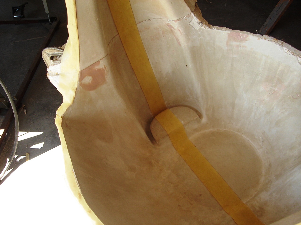
another view of pattern wax
 
This is another view of the pattern wax showing it as it transitions thru the L/H inlet area. Pattern wax can be bought with an adhesive backing or bare. The adhesive has about the same "Tackiness" as a Post it Note, so I sprayed some 3M 777 adhesive in addition to the supplied adhesive.

The pink area on the female splash is a repaired area using bondo.


Lower Splash mounted on MDH Board

This is the lower cowl mounted on a piece of MDH board and ready for the lay up of the actual mold. The splash was mounted with  plaster and an extension was added with plaster to the flange to ensure enough excess tool margin. The raw plaster will be coated with a mixture of Shellac thinned with alcohol . 5 coats of Carnuba mold wax will be applied and then a coat of PVA water soluable release coat.

I will update this blog when I return from Charleston in early June.

No comments: