Welcome to my Robin Blog.

It was suggested to me that I start a Blog on my ultralight project the "Robin". I have been working on this project for 4 years. On one of my first days at Vought aircraft, a stress man and future friend named Kenny Andersen walked up to me and said, "Aren't you the Mark Calder that designed the Wren Ultralight" Why yes I am I said. "well what have you done lately?" That was the genesis of the Robin design. The first 2.5 have been spent in the design phase. Actual construction started 1.5 years ago and has actually progressed smoothly. There have been a number of changes from the onset, but for the most part it is following my original concept. I will eventually sell plans for the Robin and make available all molded parts, fittings and welded assemblies. The Robin is designed to FAA part 103 and as such requires no pilots license to fly, although I think its a good idea to actually learn how to fly!! The actual name "Robin" was my Daughter Jamie's idea, I asked her to name the design based on my "cute little bird" theme (Wren)


Every good aircraft design has a "Mission" in mind before the actual design is started. A good designer will refer back to this mission every time a design decision must be made. Good design after all is just a series of good design decisions. On my first Ultralight design the Wren, the mission was to design a high performance low powered aircraft. The reduction of drag was the prime concern. I had been flying powered Hang gliders prior to this and because of this experience, I placed a high priority on climb performance. While most designers chose bigger engines, I chose lower drag and high aspect ratio (low span loading) wings. The Wren could out climb conventional Ultralight with up to 65 hp. The Robin follows this philosophy, but tries to improve on the performance of the Wren. Ultralight are not built by "rich" people, they offer an inexpensive means to enjoy one of the greatest experiences of my life, low speed soaring and flying.


Design Concept


The cost of an aircraft is directly proportional to its weight. , if low drag can be achieved then lighter and cheaper engines can be used. The Robin expands on the design mission of the Wren by using a longer span (40') wing and using a low speed laminar flow airfoil, (Wortmann FX 170) The leading edge of the wing on the prototype is molded fiber glass. The spar has been placed at 33% of the wing chord because the chosen airfoil is laminar over the first 32%. The aft covering is light weight Dacron Fabric. The leading edge of this fabric is purposely pinked and placed at the 32% chord point to facilitate laminar transition and elimination of separation bubbles. The main difference between the original design of the Robin and the current final design is the elimination of the single mono wheel retractable landing gear. Part 103 does not allow for a retractable landing gear. Which is really unfortunate because I spent a long time designing a really neat mechanism!!

In the course of the 4 years I have worked on the Robin, the structural design concept has evolved radically. Originally I was going to draw on the design of the Wren and use essential the same construction concepts. The original design of the Wren was heavily influenced by my Friend Steve Wood's Sky Pup design. I lived in Wichita Kansas and worked at Cessna Aircraft along with Steve. I watched his progress on the Pup and was very impressed with his concepts. I adapted the concept of using Styrofoam sheeting as the shear panels for the fuselage and the wing ribs. I did not however use the foam for the shear webs of the wing as Steve did. I originally wanted to build the fuselage of the Robin in a similar manner. Weight and the desire to not use foam for the basic structure due to the danger of fuel leaking eventually drove me to a all wood fuselage design. The wings were designed to take advantage of the Graphlite carbon pultruded material pioneered for the experimental aircraft by Jim Marske. I was familiar with this product from my experience at Bell Helicopter where it was considered in the construction of the V-22 wing.


Engine Cowl Part 6 (Final Plaster Work)

I had hoped to be farther along at this point in the project, we have had some bad weather down here that has caused a bit of a disruption in the build. Either a tornado or straight line winds of 95 mph hit our area and damaged some of my fencing. I had to use some of my free time to straighten and fix this. Then I was sent on another trip to Charleston and thats actually where I am at right now. Before I left last Monday I was able to complete both the upper and lower final splashes. I am using the plaster splash method of making the final mold masters for my cowling. This process is needed because of the desire to build a lower cowl that joggles under the upper cowl. This means that the lower cowl OML (Outside Mold Line) will transition to a negative .080 offset from the master OML surface. In order to do this a female plaster splash of the foam master had to be completed. This is where I left off on part 5. The foam master had the actual trim lines scribed into it so the location of the joggled flange could be determined.

Upper cowl splash
The first splash taken from the female was for the upper cowl. By reversing these molds, low spots become high spots and pin holes become "pimples" That means that the surface quality actually keeps improving as I get closer to the final lay up tool.

This is the upper splash. The next step will be to make the upper cowl lay up mold.


The main reason for doing all of this additional work was to make lay up mold with the flange joggled. Here is a picture of the female splash with the pattern wax laid in to simulate the joggled area.

Female Splash with pattern wax

This is a standard product called pattern wax. It comes in various thicknesses. This particular thickness is .080" I cut two inch wide strips of this wax and set them in such that they extended upward past the lower cowl trim line.


another view of pattern wax
 
This is another view of the pattern wax showing it as it transitions thru the L/H inlet area. Pattern wax can be bought with an adhesive backing or bare. The adhesive has about the same "Tackiness" as a Post it Note, so I sprayed some 3M 777 adhesive in addition to the supplied adhesive.

The pink area on the female splash is a repaired area using bondo.


Lower Splash mounted on MDH Board

This is the lower cowl mounted on a piece of MDH board and ready for the lay up of the actual mold. The splash was mounted with  plaster and an extension was added with plaster to the flange to ensure enough excess tool margin. The raw plaster will be coated with a mixture of Shellac thinned with alcohol . 5 coats of Carnuba mold wax will be applied and then a coat of PVA water soluable release coat.

I will update this blog when I return from Charleston in early June.

Engine cowl Part 5 (plaster work)

The next step in the production of the cowl tooling is to create the master plaster splash. There is only one plaster to use when you make a splash and that is US Gypsum Ultracal 30 molding plaster. I was pretty fortunate to have been able to buy 70 bags or 6300 lbs of plaster at an auction at my companies surplus sales. normally a single bag of plaster is $40/bag. I was able to get all of this plaster and a bale of reinforcing hemp for $160. I learned how to make plaster molds from a old timer at Cessna Aircraft in Wichita Kansas. I would sit out in the factory every lunch hour and watch this craftsman. I eventually came up with an idea to make some vacuum formed covers for accelerometers we were bonding to the outside of the wing of the Citation 3. I was an instrumentation technician back then and it was found that the accelerometers were causing a Mach shock wave  buzz on the ailerons. The solution was to make a little canopy like cover that streamlined the accelerometer. I was able to talk my self into a small apprenticeship with the plaster shop and I made up all of these covers on my lunch hour. It was time well spent. I learned quite a bit. There is a real trick to mixing this plaster, I use a large plastic bowl that doubled as our trick or treat candy bowl.
Ultracal 30 plaster
 An amount of plaster is first scooped into the bowl and then water is added to completely cover the plaster. The plaster will then start bubbling and the internal plaster will start to wet out. more water is added if the surface dries up. Do not stir the plaster until the water stops bubbling. This is very critical for the first layer or "Milk coat" This ensures there will be no dry spots and the coat will be consistent.
mixing bowl


this shows the plaster wetting out.


Foam master
The foam master was shot with 4 coats of automotive urethane top coat over my Friend Eds House in his spray booth. The top coat was then block sanded with an eventual grit of 2500 grit. This removed all traces of any orange peel. I decided to break up the master splash into 3 sections. The upper half would be pulled straight up, while the two side wings on the aft portion of the cowl would be pulled outboard. The reason for this was the undercut area of the L/H air inlet. 

The inlet on this master was purposely made excessively deep. The reason was to allow me the option to fill the cavity with plaster so as to allow a clean back surface and sharp break line.
cowl inlet lip being leveled

The first step in pouring the plaster back wall was to level the cowl inlet lip. This way the back wall will be parallel to the inlet lip. 


inlet lip back wall plaster pour


This is a good image of the plaster back wall after it cured. also notice that the cowl part line has been scribed on the foam master. This method created a nice clean break and limited the depth of the inlet lip in the final lay up tool. After the plaster cures 4 complete coats of carnuba mold wax was applied to the complete surface of the foam master.
divider plate

The next step was to fabricate the upper and lower mold divider. The point that I chose to divide the mold was just above a point that was scribed with a steel square set atop the mold. This point would represent the point the draft reverses and would lock in the top plaster against the foam master. a sheet of coated and tempered 1/8' masonite sheet was used. I used a contour gauge to make the coarse cut and then just continued to sand with my hand sander until the contour was close within an 1/8"
divider plate with masonite gussets

after the divider plate was trimmed, I made three 90 degree gussets. I used some Bondo to attach these to the bottom surface of the plate. The plate was then bonded to the foam master using more Bondo. Because the mold was coated with carnuba mold wax, this bond will not be too strong and will eventually beak off and clean up
Modeling clay

As I said earlier, it is only necessary to get within an 1/8" of the foam master surface. Modeling clay is pressed into the void and a sharp wooden scraper is used to remove the excess.this is a trick that all of the poured counter top guys use, this is why there are no visible part lines in their final part.
Milk Coat being added

This shows the next step, although this is a milk coat being added to the lower part of the cowl, the process is the same for the upper half. I used a sauce ladle and gently poured it on. It takes a number of tries to completely coat the surface,. but a full coat is added and allowed to almost completely cure. One of the huge advantages of using Ultracal plaster is the ability to rejuvenate the plaster if it starts to cure. This I did with the excess plaster that was left over from the Milk Coat. I placed the bowl under the mold to capture any run off, but its still a messy operation. This is why I coated my shop floor with epoxy floor paint and 5 coats of industrial wax. it makes clean up from bondo, epoxy and plaster spills a piece of cake. I will let the stuff cure and then just pop it off with a floor scraper. After the milk coat cures, plaster is mixed and clumps of Hemp are saturated and laid on top of the milk coat. Before I do that however, I will coat the drying Milk coat with a layer of wet plaster to ensure there will be no voids under the milk coat.
Hemp

 Yep, this is Hemp, closely related to the stuff you once smoked in College!!! Its actually a controlled substance that has Federal paperwork tracking it. This is the same stuff George Washington grew and all of the Hippies use to weave clothing. I am using it for reinforcement of the plaster. You work with a single handful at a time and wet it out in the plaster mixing bowl. Hemp is not cheap, a single bale sells for around $160. I got this one at the surplus auction along with the plaster for $168 total!!! I beat out a guy who wanted it for an archery target!!!  Straw works good for that and its a hell of a lot cheaper. In the past I have used Straw, dried Alfalfa and cut and dried grass, they all will work, but not as nicely as hemp.
Index pin holes being added
After the upper splash cured, the next step is to remove the divider plate and drill some indexing pin holes. I started the holes with a spade bit, but then finished them out with a tapered grinding stone. That gave the walls some draft angle. This exposed surface is allowed to dry overnight and then the plaster is coated with 4 coats of carnuba mold wax. Especially the index pin holes. The process is repeated on the lower half and a full splash is made.
attach bolt holes being added

I used a Milwaukee Sawzall  to cut the excess flange off. I then drilled a 1/8" pilot hole through both flanges. I used the pilot hole as a guide to spot face each flange with a 3/4" spade bit. I then drilled a 5/16th through hole. These are for the three bolts that will hold the lower wings on. The opposite site was completed in a similar manner and then both wings extensions were released.
Wing extensions after being released.
These came out perfectly. The surface is very shiny and extremely smooth. The excess material will eventually be cut off and the edge beveled back with a sanding wheel. On the left wing in the picture, I went a little too deep with the counter bore, no big deal. I will use clamps to hold it together during the internal splash.


Main Splash

Here is the main splash and wings assembled. I had to ask my Friend Ed to come by and help me lift off the main splash. It weighs about 175 lbs. It was important to lift straight up because that was the designed release direction. At this stage, there are a few small pin holes in the main splash and one slightly damaged area. Its not a concern. The damaged area will be fixed with bondo and the pin holes will become bumps on the next splashes. They are then easily scraped off. The next step is to add the pattern wax for the lower cowl splash and then lift the lower and upper splash. I will do the upper first and then do the lower splash. From these final splashes I will finally make the fiberglass lay up mold. That's the subject of the next blog entry.


<><><><> 

Engine cowl part 4 (Master Model).

After the Cheek Cowl foam masters were bonded in place, a single ply of 8 oz fiberglass was laid up over the foam cores. light "Milk"coats of Bondo (Automotive Body Filler) are spread over the fiberglass. I use the term 'Milk Coat" for this body filler layer. This refers to a thinned out coat of filler. MEK or Acetone is premixed with the raw filler to a consistency of heavy pancake batter. This flows very well and fills the surface cleanly. here is a little trick I use when mixing Bondo, this is a good excuse not to throw away all of those free phone books. 
Phone Book mixing Palette

Every time you mix bondo you just tear the old page out. An excellent model maker at Johnson Controls in Holland Michigan showed me this trick. So far on the Robin project I have used 1.5 phone books. If you are thinning out the bondo, you make a pool in the middle just like you are spooning Gravy at Thanksgiving!!!

I use professional grade Bondo available only at Automotive supply houses, I stay away from the popular Bondo brand available at places like Auto Zone.
As the surface is sanded smooth, a final coat of Lacquer based 'Spot" putty is squeegeed on to the surface. This is a lower viscosity, air drying product designed to fill coarse sanding scratches and minor depressions. there is a methodology used when filling and sanding the surfaces. The cheek cowl was first coated and sanded flush and flat. Long flexible sanding boards are used for this step. These products are all available at professional Auto body supply houses. My favorite is Sherwin Williams automotive paint stores. Once the cowl and cheek cowl surfaces were sanded flat and wave free, I made a "drag" or radius sweep from scrap plywood with .75" radius. This is also the radius of my foam circular sanding board. Bondo was swept between the two surfaces. A small chisel shaped wood scraper was used after the bondo started to cure to remove away the excess that escaped from the sides. Get to know your Bondo product, you will be able to judge the correct time to sand, scape or surform plane. As I finished sanding the surfaces I would sweep on the spot putty. I usually let this cure for 24 hours before I actually finish sand the putty. As you progress from step to step finer and finer sand paper is used.

Front view of cowl during shaping
Another view at this stage. The L/H cowl has been roughed in and the inlet lip is still square shaped.
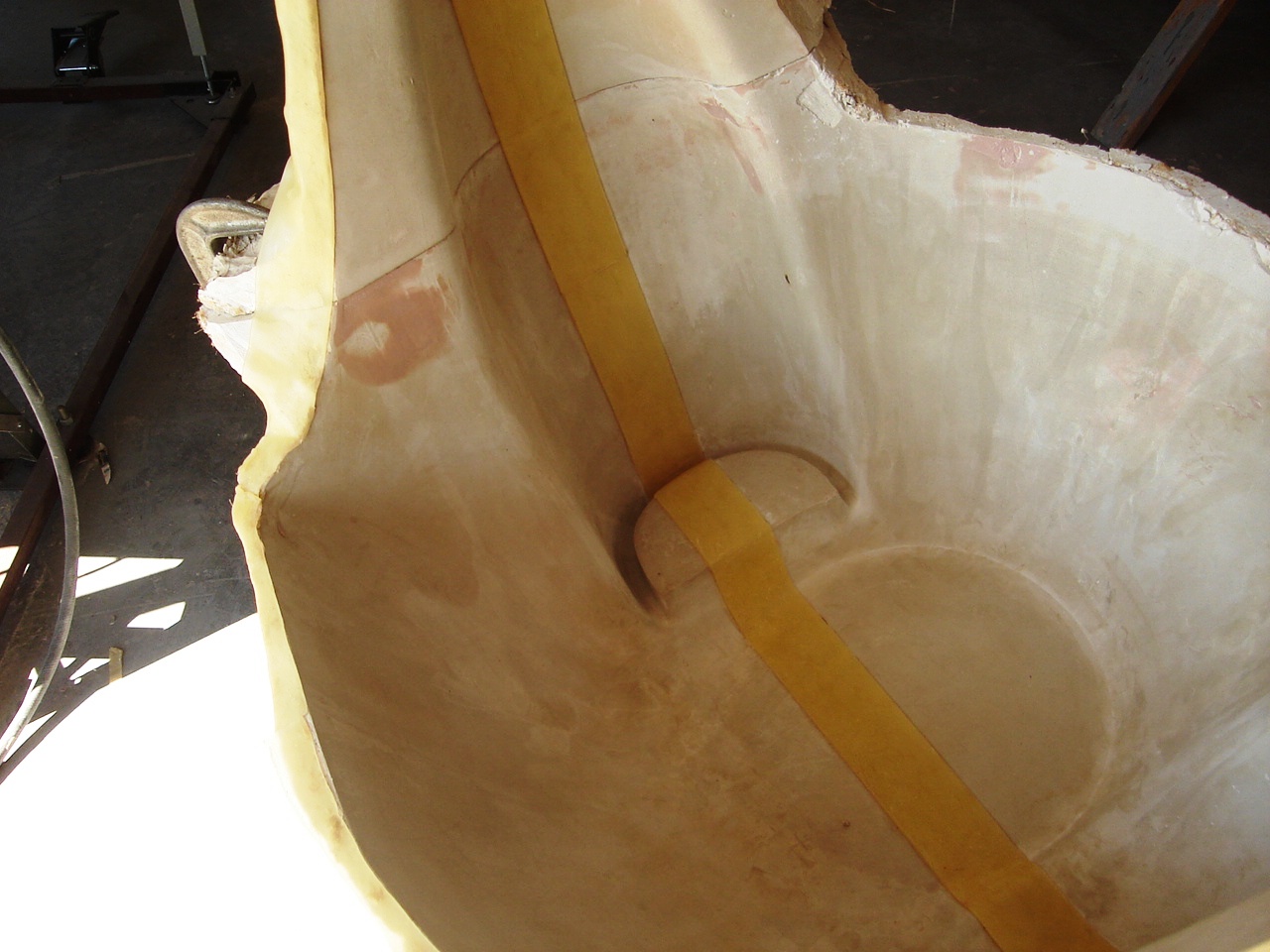


Inlet lip "Drag"

This is the technique I used to form the leading edge inlet lip. The tape was added as a guide . Bondo was mixed and swept into position. This is a long and laborious process. It took well over 5 hours of sanding and re sweeping to get this just right. Thank God for Sirius radio in my shop. This is a lot of work, I will admit this, but done correctly the results are beautiful. The anticipation of the final installed cowl, is really what keeps me going. This is truly a labor of love. Thankfully these cowls will be premolded for the plans builder. Not saying you can't do this yourself, but you will spend more money for Bondo and supplies than what I will eventually sell the cowls for.
Inlet during forming
add bondo, sand Bondo...and so on and so on. Until its perfect!!!!


The Master Spot Putty was sanded down with 180 grit. Then it was removed from the fuselage. This was easier than it sounds. It took a while to finally get the master off. I was able to get it removed with very minor damage.The next step was to construct a holding fixture that would hold the master vertical and horizontal. I want the master vertical so I can pour a plaster insert into the L/H cowl inlet. An insert is needed because any "splash" or cast of the master would be die locked in the area of the inlet. There are 4 more steps involved before the final layup mold is built. Because the cowl is designed to split through the cheek cowls, I want to have a joggled flange or "rebate" set into the surface of the lower cowl so the upper cowl sits flush. In order to do this, a master splash will need to be taken of the entire cowl . After the main splash is made, pattern wax of the desired thickness is set onto the master along the predetermined trim lines and another splash is made that reverses the contour. A second splash for both the upper and lower cowl will have to be made, From these splashes, the final lay up mold will be made.
holding fixture
This is the holding fixture I designed and built. The two perpendicular surfaces are designed so I can rotate the master 90 degrees. The top surface of the fixture will bond to the foam inside the master. I used generous scoops of Bondo for this


Fixture rotated 90 degrees.


its important to plan the work height when building fixtures. I will spend hours sanding this tool and econometrics are really important. 


Master installed on frame


The front of the master will need to be closed up. As you recall I set a 1/4" foam spacer behind the spinner master, this was so I could add the 1/16th inch spinner backing plate to close this off and decrease the gap to 1/8th inch between the spinner and the cowl


The next step was to shoot the master with a high solids filling primer. This is a catalyzed product that cures in about 3 hours. Really thick build ups can be accomplished with this product. The main splash will start after this. That is the subject of the next blog.