Welcome to my Robin Blog.

It was suggested to me that I start a Blog on my ultralight project the "Robin". I have been working on this project for 4 years. On one of my first days at Vought aircraft, a stress man and future friend named Kenny Andersen walked up to me and said, "Aren't you the Mark Calder that designed the Wren Ultralight" Why yes I am I said. "well what have you done lately?" That was the genesis of the Robin design. The first 2.5 have been spent in the design phase. Actual construction started 1.5 years ago and has actually progressed smoothly. There have been a number of changes from the onset, but for the most part it is following my original concept. I will eventually sell plans for the Robin and make available all molded parts, fittings and welded assemblies. The Robin is designed to FAA part 103 and as such requires no pilots license to fly, although I think its a good idea to actually learn how to fly!! The actual name "Robin" was my Daughter Jamie's idea, I asked her to name the design based on my "cute little bird" theme (Wren)


Every good aircraft design has a "Mission" in mind before the actual design is started. A good designer will refer back to this mission every time a design decision must be made. Good design after all is just a series of good design decisions. On my first Ultralight design the Wren, the mission was to design a high performance low powered aircraft. The reduction of drag was the prime concern. I had been flying powered Hang gliders prior to this and because of this experience, I placed a high priority on climb performance. While most designers chose bigger engines, I chose lower drag and high aspect ratio (low span loading) wings. The Wren could out climb conventional Ultralight with up to 65 hp. The Robin follows this philosophy, but tries to improve on the performance of the Wren. Ultralight are not built by "rich" people, they offer an inexpensive means to enjoy one of the greatest experiences of my life, low speed soaring and flying.


Design Concept


The cost of an aircraft is directly proportional to its weight. , if low drag can be achieved then lighter and cheaper engines can be used. The Robin expands on the design mission of the Wren by using a longer span (40') wing and using a low speed laminar flow airfoil, (Wortmann FX 170) The leading edge of the wing on the prototype is molded fiber glass. The spar has been placed at 33% of the wing chord because the chosen airfoil is laminar over the first 32%. The aft covering is light weight Dacron Fabric. The leading edge of this fabric is purposely pinked and placed at the 32% chord point to facilitate laminar transition and elimination of separation bubbles. The main difference between the original design of the Robin and the current final design is the elimination of the single mono wheel retractable landing gear. Part 103 does not allow for a retractable landing gear. Which is really unfortunate because I spent a long time designing a really neat mechanism!!

In the course of the 4 years I have worked on the Robin, the structural design concept has evolved radically. Originally I was going to draw on the design of the Wren and use essential the same construction concepts. The original design of the Wren was heavily influenced by my Friend Steve Wood's Sky Pup design. I lived in Wichita Kansas and worked at Cessna Aircraft along with Steve. I watched his progress on the Pup and was very impressed with his concepts. I adapted the concept of using Styrofoam sheeting as the shear panels for the fuselage and the wing ribs. I did not however use the foam for the shear webs of the wing as Steve did. I originally wanted to build the fuselage of the Robin in a similar manner. Weight and the desire to not use foam for the basic structure due to the danger of fuel leaking eventually drove me to a all wood fuselage design. The wings were designed to take advantage of the Graphlite carbon pultruded material pioneered for the experimental aircraft by Jim Marske. I was familiar with this product from my experience at Bell Helicopter where it was considered in the construction of the V-22 wing.


covering part 1 (Tail Feathers)

I started covering the tail surfaces. The rudder was first. This is the first time I am using the Stewart system Eco Bond adhesive. As usual there is a learning curve to go down. I will eventually re-cover the rudder, but I learned a few good lessons. The Eco bond is really good stuff, but it needs to be applied with a foam brush. The natural fiber paint brush I was using does not apply the adhesive evenly. This will make for a lumpy covering job. In the Stewart manual, they give a lot of good tips, one of them was the use of this disposable cup method.
Chinette plate and Dixie cup holder

this is a holder for the Eco bond adhesive. In the middle is a cut down Dixie cup that has been bonded with 5 minute Epoxy to the center of a Heavy duty Chinette paper plate. A fresh Dixie cup is used for the actual adhesive. Its placed in the Dixie Cup holder. This way it wont spill on you. about 1/3 a cup is all the adhesive you work with at a time. That's the length of out time you have available.
The Eco Bond is water soluble, but once it cures, its set for good.


pre coating the structure

The method I finally settled on is to pre-coat the entire structure and let it fully dry. The Eco Bond is heat activated. The fabric is placed into position and then ironed onto the frame with a iron set and calibrated to 200 degrees. The heat of the irons is extremely important. Its very important to use a good IR thermometer when you calibrate the Irons. The normal main shrink temp is 250 degrees, on a certified plane with heavier structure, the shrink is accomplished in three steps, 250 degrees, 300 and finally 350 degrees. that is way too much for an ultralight airframe.  This is the main reason I am recovering the rudder. I used the higher temp and I bent the trailing edge. Its slightly scalloped. All ultralights stop the shrink at 300 degrees.
Rudder
I am using a single wrap piece of cloth for the rudderThe first wrap will attach to the trailing edge The cloth will be wrapped over the trailing edge. The opposite side will wrap over the railing edge and attach to the cloth only. All ribs are also bonded,


Ribs being bonded
 once the adhesive dries, the fabric is tacked on using a heated iron, after everything is in place, additional Eco bond is brushed into the surface to adhere to the previous coat. Once this sets, its really on there.


beginning of the Horizontal

The horizontal came out really well. I used two separate pieces to cover this surface. Both pieced will over wrap the leading edge.


Finished Horizontal

So far the covering process added only 2.5 ounces, the real weigh gain will be the finish. Tomorrow I will finish the elevator and the ailerons. My buddy Ed will come by tomorrow and we will pull the wings. I can cover the R/H wing immediately, the L/H wing needs some repair on a plywood piece that was damaged during storage. But I should have both wings covered by Saturday. Then its on to the fuselage. after I cover the fuselage and finish the plane, I need to re assemble the wings and then build a root fairing. I decided it would be easier once I figure out where the fuselage fabric is placed.

Final Jobs Before covering

Merry Christmas!!   For the last 3 years, this vacation has been my chance to make real progress on my project. I had hoped to be able to take off most of the month, but we had a huge number off RFQ's ( Request for Quote) in the last month. I normally work on an advanced composite design project, unless we have quotes to do. Had my project just been my Advanced R&D project, I could have taken off. Oh well. Anyway, I got smart and bought 3) 55 gallon Barrels and set the Robin on top of them. This also gave me a chance to weigh her with the wings on. I am not going to make ultralight weight without a Ballistic Parachute. I am close, 246 lbs, but that without cover. On this plane however is a ground adjustable CGS prop that weighs 9.5 lbs. I am using that Prop to dial in a fixed pitch Spruce prop that will weigh 1.5 lbs. Subtracting that weight from the total and that gives me a weigh allowance of 16 lbs for covering. I have estimated 18 lbs. Anyway, with a Second Chantz http://www.secondchantz.com/ ballistic chute, I will be a legal Ultralight. as I mentioned earlier in my blog, by wing is 19 lbs over weight. 5 lbs of that weight is excessive resin packed into the void between the round carbon pultruded rods. The other excessive weight is the fiberglass in the spar and the leading edge. I have begun working on a redesigned wing, I do not like the current attach method either. This and the desire to reduce weight has driven me to a redesign. My new wing design will be constructed of plywood and graphite pultrusions. There will be a fixed center section, this one redesign will save 5 lbs, due to elimination of the overlapping spars. The attachment method will be more akin to the beautiful German sailplane designs I have been studying. There will be no physical attachment of the ailerons or the wing other than two main shear bolts. All fore and aft and vertical shear will be reacted by sockets and pins. The breakdown of the wing will be greatly simplified by this redesign, I would anticipate that installing the wings or breaking them down will take about 10 minutes.
up in the air
If my span was one foot longer, I couldn't build her in my shop. man I miss my old shop in Wichita!! I picked these barrels up at a local Feed store, believe it or not, but they were marked as having concentrated lime juice from Iran!!!  I thought we had an economic embargo in place for 25 years??? The scales are also shown in this view. I needed to elevate the plane so I could walk around it without ruining my back. I needed access to bottom so I could terminate the aileron cables. I designed the wire routing so that they could pass from root rib to root rib without passing through any redirection pulleys. In the root of each wing rib, I added 2 split Piper Style cable guides. The cables are being redirected less than 1/2 of a degree. Very acceptable!!! The ailerons actuate with very little friction.
Aileron Cables

Here is a view looking fwd from the tail . This area is accessible after the seat is removed. the Main wing shear pins are also shown. These ended up being 3/4"  grade 8 pins. They are modified automotive grade 8 bolts. Strength wise, automotive Grade 8 bolts are stronger than typical aircraft bolts. AN aircraft bolts are actually equivalent to Automotive grade 5 bolts, the big difference is the pitch of the thread.  The cables break at 3 AN-115 shackles with 3) 3/16" clevis pins.
cable cutout

This was a little "oops". At the limit of the bottom travel of the aileron, the turnbuckle interfered with the upper aileron fairing. 3 minutes of work with the rotary rasp and a circular sanding wheel, and all was fixed. The aileron cable pulleys are free floating and seek their own angle thru the range of aileron travel. All 4 pulley brackets are identical. The design has two cotter pins that retain the cable when the lines are slack. For inspection purposes, there will be an inspection cover in the lower covering. The Ailerons are Frise type ailerons.


The big issue with a long sailplane wing is adverse yaw. Plain hinged ailerons will generate more drag when deflected downward than upward. This is due to the dynamic pressure being greater on the lower surface than the upper. Since drag is a function of dynamic pressure, the down traveling aileron will normally have more drag that the up traveling aileron. This causes the nose to yaw in the direction opposite of the turn. The pilot must anticipate this and lead with rudder prior to staring the bank. This makes  for a poor flying airplane. Adverse yaw is usually eliminated by the use of differential bell cranks. But this would have required 1 bell crank bearing and two Heim or Rod ends per aileron. That equates to about $200 per airplane. The alternative is a Frise style aileron. I chose the Frise because of three reasons, it was lighter, cheaper and the dipping of the nose causes an increase in drag and an aerodynamic balancing force that reduces control stick forces. The German Gliders that I have been flying, have friction and aerodynamic forces so low, there is very little force required.
Elevator Tip Cap

One of the last jobs I did today was trim and bond the elevator tip cap. Tomorrow, I will add a small foam bulkhead that closes out the Horizontal and the elevator tip caps.


I have three more jobs to finish before i can start covering, i need to install the Primer tubing and install the Throttle. once they are finished, I have only to finish installing the Rudder and Vert. Fin tip cap. I held off until this week, and it turned out to be a good thing, My  Buddy Ed Gardner http://mmwauto.com/ gave me a very cool Christmas gift, one that everyone on this blog will eventually appreciate. Its a 170 degree digital Video recorder. Its so small I can mount it in the Vert. fin Tip cap. I will record my first flight and taxi tests with this.

Canopy Latch, and Windshield.

Well I am finally finished with the canopy. This is one of the last jobs I needed to complete before I start covering her.  On Saturday I was joined by Jay Swindle, Jay is a local Texan and one of my earliest Blog followers. We worked together all Saturday afternoon completing the canopy latch. Since my last blog update, I installed the Engine Primer pump. There is a small fuel port on the reed valve housing that is designed to accept an external primer. This is convenient because of the closed cowling of the engine. I decide to mount the primer on the L/H inboard longeron. To avoid removing any area in the  longeron I decided to mount the Primer on a 3/4" plywood stand off block, that block in turn was bonded to the the longeron with T-88 adhesive.

Fuel primer


The primer bracket was made from .063" 2024-T3 sheet. I bent this part on  a combination sheet metal shear, roller and brake. I bought this tool years ago when the price of steel was low. I paid one dollar a pound for this 350 lb tool.


Multi- Function brake/shear/roller

This is a view of my combination tool. in my plans drawings there is a line on every flat pattern that signifies the center line of the bend. That center line is directly in the middle of the upper radius plate. I usually measure back from one edge and offset that dimension for the width of the "V" groove. A machine square is used to square it to the face of the "V" groove. The flat patterns also account for the stretch that the part will under go when it is formed. I learned this skill by drawing flat patterns by hand on the 747 section 41 fatigue redesign program. I believe I drew over 5000 patterns. After that many, the process kind of sticks with you.
Primer Bracket and Uni Bit
One more word about the Primer bracket, and that is the process of drilling a large diameter hole in thin sheet metal. The best method I have found so far is the Step drill or Uni Bit. At $38 bucks for one bit, its a bit pricy, but well worth the price. As you can see the hole it drilled was very clean.


Canopy Centering clip

I needed 4 of these, canopy centering clips. when the canopy rotates to the closed position, these clips will center the canopy so the latch pin aligns


L/H canopy latch

Here is what I ended up with for the canopy latch. I had a design already drawn, but it was way too complicated and I didn't feel like building it. I wanted something simpler. Jay and I were brainstorming on this and we decided to take a ride to Midway Airport and see how the Germans did it on their sailplanes. What I ended up with is kind of a hybrid between the Schweitzer 1-26 and the Grob 103. There is a fwd and aft detent plate at the front of the latch handle and an adjustable home made eye bolt as the rear latch.

rear canopy latch detail
I took a 1/4" bolt and then made a lug out of 1/8' 4130 steel. I brazed the two together. I purposely made the rear post adjustable vertically to allow for adjustment to the center line of the latch pin. The latch rod by the way is 3/8 hydraulic truck brake line. I cut off a 5/16" bolt and put a 15 degree taper on the end of it. That was then brazed into the latch tube.


Canopy installed
Then it was on to the next big job, final installation of the canopy windshield. I attached the canopy with 200 Avex Countersunk pop rivets. The outside of the canopy was touch countersunk to accept the head of the rivet. The canopy installed very cleanly. There is a protective plastic covering still on the outside of the canopy. I will keep it that way until just before first flight. 


Another view of the canopy
This shows the reason for the yarmulke, the wind shield is flat wrapped with a single curvature. All compound contour is confined to the yarmulke. It also doubles as a sun shield. I'm pretty pleased at the way this came out

Canopy quick release and disconnect plug

I finished fabrication and installation of the canopy quick disconnect hinge. I started modification of the fwd turtle deck to accept a square cut out for the disconnect plug. The socket side of the disconnect cable is designed to snap into a square cutout. I decided to modify the fwd turtle deck rear bulkhead to remove the core and close out the the area of the plug. The close out has a thick build up of fiberglass doublers to make up the required thickness of the disconnect plug.
Quick disconnect hinge showing the 3/8" spring pin
This is a picture of the final installation of the quick disconnect hinge. The pin had to be split and spliced so it could be installed.


Rear view of release pin
This is a view of the release pin. I drilled and then reamed this hole to allow exactly .002" clearance. The pin removes with 7 lbs of force with no lift load. The square cutout in the canopy is the location where the disconnect cable will be located. a strain relief will be added to the cable and attached to the emergency lanyard so that it is removed the cable will automatically be disconnected


core foam removed and edges beveled.
This is the start of the bulkhead reinforcement. The core was split using the Multi- tool and then cleaned out using the same tool. The exposed foan was then bevel sanded and the exposed fiberglass was cleaned up with 100 grit sand paper. I put a piece of tape on the opposite side to cover the old hole.


close out with glass doublers
After the glass thoroughly cures I will lay out the rectangle opening for the cable plug.

Next job is the canopy patch and the emergency release handle.


The next job will be the last before covering, I need to rig thew aileron cables and set the disconnects,

Instrument panel update

Not much progress to report. I went on Vacation to visit my Family in Detroit, so I just got back on the  plane last Sunday.  I completed the panel wiring and terminated all of the panel leads into a common plug. The mate is attached to the fuselage. I am working on a quick release hinge that I can use as an in flight emergency egress, but also as a quick release for the whole canopy. I want the canopy readily removable so I can attach a hoisting harness to the landing gear frame and the main Wing attach pins. Initially I will be operating out of Midway airport in Midlothian Texas. My friend  Pete and his wife Carol own "Big Q aviation" http://www.bigqaviation.com  They have 4 hangers on the field. I will be hoisting the Robin up to the ceiling in one of them.
Belite Instruments

The instrument panel was attached with 3/16" nut plates riveted to a .063" thick piece of precured NEMA electrical insulator fiberglass. That in turn was bonded to the instrument frame. I wrung out all of the circuits and checked the function. The switch on the right is the Engine kill. The switch at the bottom is the panel power and the potentiometer to the right of the power switch is the LED dimmer control. The center space in the panel will eventually have an audio -Vario. The lower space above the dimmer control will be a holder for my I- Phone. I  found a cool App for the I Phone that has a moving aeronautical chart display. its synced to the phones GPS. pretty damn cool!! The world lost another Thomas Edison when poor Steve Jobs died.
Spaghetti view
There are two large strain relief loops in the wire cable. this will allow the panel to be easily removed for service. This fwd section of the canopy will be fabric covered.
The next job on the canopy will be to install the latch and then the windshield. My plan is to complete every job short of covering by the end of the first week of December. I will have almost 4 weeks off after that and I plan on completing the covering. I have all of the materials on hand so the job should go smoothly. I purposely designed the ribs with 3/4" width so I can bond the fabric to the ribs instead of rib stitching.
 There are two large strain relief loops in the wire cable. this will allow the panel to be easily removed for service. This fwd section of the canopy will be fabric covered.
The next job on the canopy will be to install the latch and then the windshield. My plan is to complete every job short of covering by the end of the first week of December. I will have almost 4 weeks off after that and I plan on completing the covering. I have all of the materials on hand so the job should go smoothly. I purposely designed the ribs with 3/4" width so I can bond the fabric to the ribs instead of rib stitching. 

Instrumentation Cable

 This shows the Fuselage side termination. In addition to the wiring plug and socket, there is also a quick release for the Pitot tubing. I will modify the rear bulkhead with a slot so the cable sits under the hinge


Hinge parts


So here is what I finally came up with for a removable canopy hinge. I wracked my brain for a few days on this one. I have two design problems to solve. I need to be able to remove the canopy as a normal course of operation and I need to get rid of it if I have an emergency in flight. The part in my hand is permanently attached to to the canopy. The hinge, hinge plate and the hinge pin are permanentlyy attached to the fwd Turtle deck at the location of the previous hinge. 
Assembled Hinge


This shows the location of a 5/16" spring pin. The loading is reacted Heel to toe, between the upper flange and the pin. In flight there is about 100 lbs of lift load on the canopy, this lift load is taken by the spring pin. The pin passes through the retainer plate, hing plate and the last bulkhead, which has a wood bearing block in the canopy. A lanyard is attached to the spring pin and it exits out of the instrument panel on the R/H side (I am right handed) The emergency lanyard has a 3 inch relief loop that is attached to the instrumentation cable. One hard pull will release both the canopy and the plug. For ground operation, the lanyard is pulled only nought to release the spring pin.

Instrument panel, canopy and tail fairing Part 2

This is an update to the previous post. I am working on the modification of the Canopy frame to accept the instrument panel and increase the knee room. I laid out the trim of the solid bulkhead and then cut it out of the existing frame. The biggest problem was how to reinforce the core under the instrument panel attach screws. The core is 4.5lb/cu ft urethane foam. It will immediately crush when the screws are tightened up. I marked the location of the screws and then used a 1/4" drill to route out all of the foam within a 1/2 inch in each direction. The void will be filled with dry Micro balloon. This is Micro mixed to the consistency of dry dough. To ensure a good bond, the cavity is coated with raw epoxy.

Bulkhead and lower shear pane trimmed out
The tab outs are around the fabric stringers. The attach screws are between each of the stringers.

The plywood gussets are designed to smoothly transition the fabric  from a faceted flat to the curve of the bulkhead.


This is a good picture of the tab outs. The urethane foam core is shown. The lower shear panel was cut back, this exposed a Styrofoam edge. I do not like raw Styrofoam in the fuselage. One time during the Lakeland Airshow when I was building the Wren, one of the only other manufactures I ever met who was not very friendly came up to me and started yelling at me??? He complained that I was pushing the spirit of part 103 and I should just go back to Kansas and stop this madness!! He was quite famous and unfortunately(or fortunately) he is no longer with us. He was criticizing me for building a fuselage out of Styrofoam. Evidently he didn't level the same criticism at Steve Wood for his Sky Pup, but in any case, he told me that a single gas spill could drop me out of the air!!  That night around 2 am I heard a noise outside my camper , when I ran up to the Wren, she was soaked in gas. The whole lower panel was dissolved away. I sat up all night and repaired the fuselage by splicing in foam with 5 minute epoxy. I completed all of the repairs 30 minutes before the ultralights flew later that day. When Mr Pseudo-famous walked by the flight line, the look on his face proved beyond all doubt he was responsible!!

Anyway, that's why I don't like Styrofoam in a primary load path.!!

Shear panel close out
This is the closeout of the exposed shear panel edge. The technique here is to cut a 45 degree wedge away from the foam up to the cured glass. Dry Micro is then forced into the corner A layer of glass is then laid up over the exposed foam. When the micro cures, it forms a wedge shaped gusset. Once its fully cured (72 hours @74 degrees) the edge will be rounded over with a sanding block to keep from scraping the pilots legs.


boo saving me from a Frisbee attack
I live on the edge of the Hill country about 40 miles south of Dallas. Just south of me about 10 miles, it starts to open up like the Texas you see in the movies. There are lots of wild animals and recently there have been a number of pet dogs and cats that have been attacked and killed by mountain lions. But that's not the nastiest threat we have in Midlothian. While I was working away out on my shop minding my own business, a wild Frisbee attacked me, luckily My good ole boy Boo was there to protect me!!  I'll tell you, I will never have any dog other than an Australian Shepard. Its really fun to have a very smart dog!!

Instrument panel, canopy and tail fairing

all of my parts have come back from paint. In the time I was waiting for them, I finished calibrating the fuel tank gauge and tested out all of the instrument. I laid out a wiring schematic and I found a 12 pin power cable plug/socket combination that will serve as a quick disconnect between the fuselage and the Canopy. I want to be able to quickly remove the canopy because I will be hanging the robin from the rafters of my friends hanger. Under me will be 4 sailplanes.  
canopy Frame and Yarmulke

The fwd hinge of the canopy is actually an open hook. The canopy will have to be rotated beyond 90 degrees to release it. there will be two side latches that have yet to be fabricated, that lock the canopy down. The next job I have to work on is modifying the instrument panel bulkhead to add the knee relief we saw that I needed when my friend Mike was sitting in it.


Instrument Panel
Its pretty obvious in this view the modification that needs to be done to the panel Bulkhead. Beneath the canopy is a horizontal foam and glass shear panel. this too will be cut back to the intermediate foam rib shown in the previous picture. The instruments for the first flight will be a combination  CHT/EGT temp gauge, fuel gauge, inclinometer, airspeed and AGL altimeter. Later I will install an Audio Vario in the upper left. The lower middle will be used for a Velcro mount of my I Phone and  Hand held VHF radio.  


Rear fairing being bonded in place
After I trimmed the rear fairing to accommodate the elevator travel, I realized the fairing would be quite narrow and prone to damage if the whole fairing was left on the Horizontal. S i carefully cut the fairing in two and waxed the inside of the lower fairing. I then set the upper and lower fairing back into the mold and laid up a flange that is bonded to the upper fairing only. This will make a nice clean break and keep the fairing halves bonded to their mating structure.


Vert Fin tip cap

pretty self explanatory!!!


Rudder Tip cap
Same with the rudder, looks like my thumb was covering the lens of my I-phone.


In addition to working on the previous components, I cleaned the Shop and re arranged the equipment to clear the wing tips. The only problem is when i reinstall the wings, I cannot get around in the shop. So I have decided to construct a center set of saw horses to elevate the fuselage 3 feet, I will also build two supports for the wings. I am not very happy with my wing attach design, because I will be redesigning the wings to reduce weight, I have also decided to make a fixed center section and have an external joint. The new design will allow for rapid installation of the wings and automatic disconnect for the ailerons.

Sensor wiring and routing

 I woke up yesterday and checked the stats on this blog, and it was thru the roof!! All thanks to my fellow EAA members logging in. It seems the EAA light sport magazine published a link to the EAA thread I started on the Robin.   Welcome all my EAA friends!!

I am currently waiting for my friend Ed  http://mmwauto.com/index.php/services.html to finish painting the horizontal/Vertical fin fairing , the canopy Yarmulke and the tip caps for the vert fin and rudder.Meanwhile I started installation of the engine wiring and instrumentation. I bought a set of all electronic gauges from Jim Weibe http://www.beliteaircraft.com/  I was particularly interested in his electronic fuel gauge. Its unfortunate that I did not plan for these gauges from the beginning. I could have incorporated a flat section into the fuel tank that would have accepted the sender. However, the method I came up should work just fine. The fuel sensor appears to be a variable capacitance sender. There is a outer tube that acts as one plate and a center 14 gauge wire that acts as the other plate. As the fuel enters this tube, the fuel will act as a variable dielectric and upset the balance of a capacitance bridge. The difference is read on the fuel gauge. There are two standard lengths of the senders, 12 and 24 inches. You can trim the probe to any length you need. The base of the probe mounts to a 3/16" thick plate that is drilled and tapped. To lessen the weight and add additional bond area, I drilled lightening holes between the threaded holes. I countersunk both faces so Flox, which will be forced through, will act as a positive lock. I started the process by filling the  threaded holes with carnuba wax. I coated the fasteners with carnuba and inserted them into the plate. I sanded the bond surface with 100 grit paper and then wiped the bond surface with MEK. This is then carefully set aside and not allowed to come into contact with any contaminants.

Fuel level sender base
This looks like a real mess, but after it cures, the mating surface will be ground clean and flat. a flox radius was swept all around the perimeter and inside. This serves to increase the bond area. One trick I like to use is to add 3M 777 spray into the resin before I mix the flox in. I have found that this dramatically increased the peel strength of the bond. This is a poor mans method of creating a 'Toughened Resin" system The all composite 787 uses a toughened resin system. The idea is to add elastomeric polymers to the resin matrix. The addition of an elastomer or rubber molecule into the matrix, allows the brittle epoxy to have a slight amount of give. Since all bond stresses concentrate on the edges, this additional give keeps the edge from delaminating or peeling away. The effect is dramatic. I used a toughened resin on the wing spar of the Robin and I conducted my own testing . Without the toughener, the peel strength was around 100 psi. With it, 1000 psi, a ten fold increase. Be forewarned, I have not tested this in the hot/wet environment and I understand that there is some degradation. There are commercial tackifiers available that are used in the VARTM industry that not only increase the peel strength, but also increase the hot/wet properties. I installed the cylinder temp sender and the EGT sender. I then routed the engine wiring. On the computer in the evening I will be laying out the pattern for the gauges. I am also looking for a lighter weight throttle quadrant. if I cant find one commercially available. I will design and build my own.
Wires after routing

This shows the sender installation.
I want to be able to remove the canopy when I am working on the plane and when it is being suspended from the hanger ceiling at my local airport. So that means that all wiring must terminate right at the canopy hinge with a multi pin plug. I am looking for that plug right now. I will need to route a Tygon tube from the wing pitot to the airspeed pressure sensor mounted behind the airspeed gauge. This tube will also have to route to the area of the plug. I need to figure out a quick disconnect not only at the canopy hinge, but at the wing root also.

keyhole slot


I had to add a Keyhole slot at the base of the tank fairing. so it could be removed without disconnecting the wires. I will have to add two more on both ends to accommodate the throttle cable.


Iso view of the engine installation


This shows the additional baffle plate I  added to firewall so I can seal the gap around the cheek cowls. I am using the stock carb. air filter, but I would like to find a more compact unit, as it is now, I have to bend the filter aft inside the cheek cowl. It will work, but I would like to find a better  filter.

So a little searching and some more scrounging and I should have the instruments all installed. It feels good to make final saftied connections. the last job before covering will be to re-rig the wings and mount the ailerons and route the aileron cables. Also today I bought 3 spring scales and I weighed the whole mess!! No estimating, because all of the parts are completed. assuming 18 lbs for complete cover and paint (should be conservative) I weight 243 lbs!!!! That is a huge relief, but this is the reason the prototype has no brakes or starter. however, my initial prop weighs 8 lbs, this will reduce to 1.5 lbs when I finally choose the correct diameter and pitch. I will ask CGS props to carve me a fixed spruce prop. If I  have time I will carve my own. I use the Fred Weick method he outlined in a NACA pub from 1929. Come think of it, I will carve my own and detail it in the blog, its really a very simple process and 90% of the work can be done on a band saw.

Horizontal/Vert fin fairing

One of the last "big" jobs I need to finish is the fairing between the Vert fin and the horizontal. There is a natural gap between these two parts and passing through this space is the elevator. A slot will be cut in the fairing to allow for full up travel of the elevator. Because I cannot make a lightweight "insitu" fairing out of foam, I decided to make a full mold. The fairing will be laid up in this tool with one 3.2 oz fiberglass surface ply and one layer of 8 oz graphite.
Tape being applied to exposed plywood
 The project started by covering all of the exposed plywood with aluminum duct tape. We used to call this 500 mph tape at Cessna, we used it to attach external instrumentation wires on the Citation 3. The white strips on the middle of the Vert fin leading edge are adhesive backed 3" wide 60 grit sand paper. I will uses these to contour the floral foam blocks that are attached later. I have used this technique to make contoured sanding blocks for automotive body repair. If the car I am working on was too severly damaged in this area, I would find an umdamaged car and make contoured sanding blocks out of styrofoam.
1 lb/c ft Floral foam blocks
The area where the fairing is to be built is stuffed with floral foam blocks. Notice how the sand paper has some foam dust on it. The blocks are rough cut using a wood saw and a hacksaw blade. The first contour cut will be the side profile of the fairing. Before starting the foam blocking, I used a piece of welding rod and taped it to the horizontal and the leading edge. I used two pieces of tape on each end so the wire would have an established tangency. The fairing needs to smoothly blend between these surfaces.I made a tracing on a piece of poster board and I will use this as a guide when I cut the side profile.

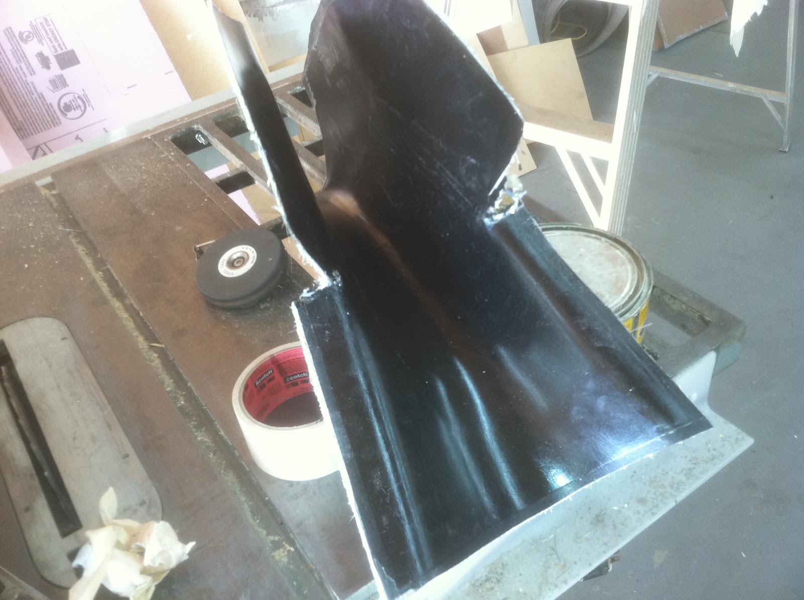
Foam after contouring
After the side profile was shaped, the foam was sanded to a pleasing shape using another block of foam. Once I was satisfied with the shape, I laid up 2 light weight plys of fiberglass and let everything cure overnight. The next day, I started coating the glass with Bondo. I have gotten pretty good working with Bondo. I attribute this to having grown up in the Detroit area. As a 16 year old driving around, every spring was spent repairing rust from all the salt on the road.
The technique for using Bondo is to lay on multiple thin layers. Sanding in between each coat.
multiple layers of Bondo

36 grit paper on an air powered file board is used to rough contour the bondo. As the shape gets closer, finer and finer sandpaper is used. The last grit will be 180. There is no need at this stage to use any finer. A word about materials here is in order, do not rely on the chain stores (Auto Zone...) for your materials. Find a body shop supply business. They will have the professional grade body fillers and sand paper. The price is always less than the inferior commercial products.
Final Bondo Coat
After you are satisfied with surface and it is wave and pit free, block sand the surface with 220. The next step is to coat the surface with professional grade Spot putty. Spot putty is a lacquer based product that dries by evaporation. The thicker the coat, the longer it takes to dry. Spot putty is not used to contour the surface, its used to fill the sanding marks an very slight depressions.
Spot putty applied


I usually let this dry for 24 hours .


Final sanding after application of Spot Putty

This will give you an idea about how much of the spot putty is left after sanding. The spot putty is first sanded with 220 grit, and finish sanded with 320. at this point I taped up and papered the rest of the plane and applied 5 coats of carnuba mold release paste wax.


PVA Poly vinyl acetate

On top of the polished wax, 6 coats of PVA were sprayed on. The coats were allowed to thoroughly dry between applications. Once the surface has been coated, the PVA forms a film that will act as the release surface


Texas AutoClave
Between coats, I rolled the fuselage out into the "Texas Autoclave".  85 degrees F here today, in the middle of October. Texas is a wonderful place to live 3/4 of the year. True Texans however are solar powered and don't care a whit about the heat of summer, in fact they say its a natural Yankee barrier!! They curse the day Airconditining was invented!!!
Gel Coat being applied

Using my Gel coat gun, I sprayed 1/2 a pint of Gel coat. the gel coat is allowed to cure until tacky and then raw resin is applied over the gel coat and pieces of non directional mat is applied. It took about 2 hours to cure enough so I could pull the mold off.


Fairing Mold
Tomorrow I will lay up the fairing.


Fairing in position


 Finished fairing!!! 1.0 ounces.

The fairing will be bonded to the horizontal