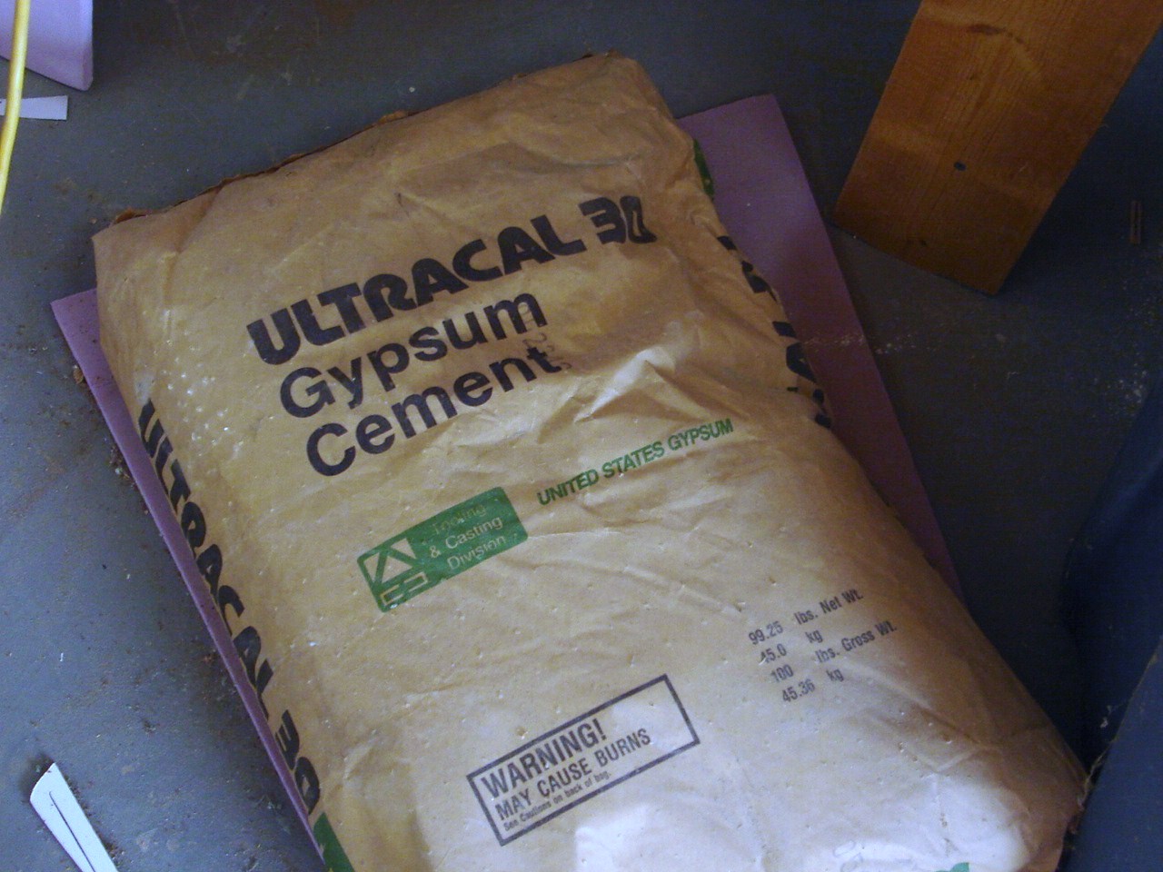
The next step in the production of the cowl tooling is to create the master plaster splash. There is only one plaster to use when you make a splash and that is US Gypsum Ultracal 30 molding plaster. I was pretty fortunate to have been able to buy 70 bags or 6300 lbs of plaster at an auction at my companies surplus sales. normally a single bag of plaster is $40/bag. I was able to get all of this plaster and a bale of reinforcing hemp for $160. I learned how to make plaster molds from a old timer at Cessna Aircraft in Wichita Kansas. I would sit out in the factory every lunch hour and watch this craftsman. I eventually came up with an idea to make some vacuum formed covers for accelerometers we were bonding to the outside of the wing of the Citation 3. I was an instrumentation technician back then and it was found that the accelerometers were causing a Mach shock wave buzz on the ailerons. The solution was to make a little canopy like cover that streamlined the accelerometer. I was able to talk my self into a small apprenticeship with the plaster shop and I made up all of these covers on my lunch hour. It was time well spent. I learned quite a bit. There is a real trick to mixing this plaster, I use a large plastic bowl that doubled as our trick or treat candy bowl.
 |
| Ultracal 30 plaster |
An amount of plaster is first scooped into the bowl and then water is added to completely cover the plaster. The plaster will then start bubbling and the internal plaster will start to wet out. more water is added if the surface dries up. Do not stir the plaster until the water stops bubbling. This is very critical for the first layer or "Milk coat" This ensures there will be no dry spots and the coat will be consistent.
 |
| mixing bowl |
this shows the plaster wetting out.
 |
| Foam master |
The foam master was shot with 4 coats of automotive urethane top coat over my Friend Eds House in his spray booth. The top coat was then block sanded with an eventual grit of 2500 grit. This removed all traces of any orange peel. I decided to break up the master splash into 3 sections. The upper half would be pulled straight up, while the two side wings on the aft portion of the cowl would be pulled outboard. The reason for this was the undercut area of the L/H air inlet.
The inlet on this master was purposely made excessively deep. The reason was to allow me the option to fill the cavity with plaster so as to allow a clean back surface and sharp break line.
 |
| cowl inlet lip being leveled |
The first step in pouring the plaster back wall was to level the cowl inlet lip. This way the back wall will be parallel to the inlet lip.
 |
| inlet lip back wall plaster pour |
This is a good image of the plaster back wall after it cured. also notice that the cowl part line has been scribed on the foam master. This method created a nice clean break and limited the depth of the inlet lip in the final lay up tool. After the plaster cures 4 complete coats of carnuba mold wax was applied to the complete surface of the foam master.
 |
| divider plate |
The next step was to fabricate the upper and lower mold divider. The point that I chose to divide the mold was just above a point that was scribed with a steel square set atop the mold. This point would represent the point the draft reverses and would lock in the top plaster against the foam master. a sheet of coated and tempered 1/8' masonite sheet was used. I used a contour gauge to make the coarse cut and then just continued to sand with my hand sander until the contour was close within an 1/8"
 |
| divider plate with masonite gussets |
after the divider plate was trimmed, I made three 90 degree gussets. I used some Bondo to attach these to the bottom surface of the plate. The plate was then bonded to the foam master using more Bondo. Because the mold was coated with carnuba mold wax, this bond will not be too strong and will eventually beak off and clean up
 |
| Modeling clay |
As I said earlier, it is only necessary to get within an 1/8" of the foam master surface. Modeling clay is pressed into the void and a sharp wooden scraper is used to remove the excess.this is a trick that all of the poured counter top guys use, this is why there are no visible part lines in their final part.
 |
| Milk Coat being added |
This shows the next step, although this is a milk coat being added to the lower part of the cowl, the process is the same for the upper half. I used a sauce ladle and gently poured it on. It takes a number of tries to completely coat the surface,. but a full coat is added and allowed to almost completely cure. One of the huge advantages of using Ultracal plaster is the ability to rejuvenate the plaster if it starts to cure. This I did with the excess plaster that was left over from the Milk Coat. I placed the bowl under the mold to capture any run off, but its still a messy operation. This is why I coated my shop floor with epoxy floor paint and 5 coats of industrial wax. it makes clean up from bondo, epoxy and plaster spills a piece of cake. I will let the stuff cure and then just pop it off with a floor scraper. After the milk coat cures, plaster is mixed and clumps of Hemp are saturated and laid on top of the milk coat. Before I do that however, I will coat the drying Milk coat with a layer of wet plaster to ensure there will be no voids under the milk coat.
 |
| Hemp |
Yep, this is Hemp, closely related to the stuff you once smoked in College!!! Its actually a controlled substance that has Federal paperwork tracking it. This is the same stuff George Washington grew and all of the Hippies use to weave clothing. I am using it for reinforcement of the plaster. You work with a single handful at a time and wet it out in the plaster mixing bowl. Hemp is not cheap, a single bale sells for around $160. I got this one at the surplus auction along with the plaster for $168 total!!! I beat out a guy who wanted it for an archery target!!! Straw works good for that and its a hell of a lot cheaper. In the past I have used Straw, dried Alfalfa and cut and dried grass, they all will work, but not as nicely as hemp.
 |
| Index pin holes being added |
After the upper splash cured, the next step is to remove the divider plate and drill some indexing pin holes. I started the holes with a spade bit, but then finished them out with a tapered grinding stone. That gave the walls some draft angle. This exposed surface is allowed to dry overnight and then the plaster is coated with 4 coats of carnuba mold wax. Especially the index pin holes. The process is repeated on the lower half and a full splash is made.
 |
| attach bolt holes being added |
I used a Milwaukee Sawzall to cut the excess flange off. I then drilled a 1/8" pilot hole through both flanges. I used the pilot hole as a guide to spot face each flange with a 3/4" spade bit. I then drilled a 5/16th through hole. These are for the three bolts that will hold the lower wings on. The opposite site was completed in a similar manner and then both wings extensions were released.
 |
| Wing extensions after being released. |
These came out perfectly. The surface is very shiny and extremely smooth. The excess material will eventually be cut off and the edge beveled back with a sanding wheel. On the left wing in the picture, I went a little too deep with the counter bore, no big deal. I will use clamps to hold it together during the internal splash.
 |
| Main Splash |
Here is the main splash and wings assembled. I had to ask my Friend Ed to come by and help me lift off the main splash. It weighs about 175 lbs. It was important to lift straight up because that was the designed release direction. At this stage, there are a few small pin holes in the main splash and one slightly damaged area. Its not a concern. The damaged area will be fixed with bondo and the pin holes will become bumps on the next splashes. They are then easily scraped off. The next step is to add the pattern wax for the lower cowl splash and then lift the lower and upper splash. I will do the upper first and then do the lower splash. From these final splashes I will finally make the fiberglass lay up mold. That's the subject of the next blog entry.


No comments:
Post a Comment