The Cyclone
I designed and built a 3rd airplane. It was called the Cyclone. I never finished it because I was moving too much and the plane became the subject of a lawsuit. The original guy who paid me to design the plane went bankrupt 2/3 of the way thru the project. I had been hauling the project around fro years until I finally sold it to a guy in Minnesota. Anyway, the Cyclone was designed to be a Canadian rules Ultralight. It was powered by a 65HP Rotax and designed as a STOL one man plane. It has an all aluminum 37 ft span constant chord wing with an 8 foot flap and drooping ailerons. The flaps controlled a differential aileron mixer that blended the Aileron differential. The lower fuselage was designed to accommodate a strake angle that matched a Grumman Aluminum Canoe. The canoe doubled as a cargo pod. The plane was designed to a gross weight of 1200 lbs. it was intended that a fully dressed elk and camping gear could be loaded in the canoe.
 |
| The red paint is a sandable primer |
The front of the fuselage was a two half molded shell of Kevlar and graphite. There is a great deal of Wren heritage in this lay out.
 |
| Cyclone with Daughter Hovercraft in background |
The wings were conventional aluminum construction. the ribs were all hydro formed. Each wing each had a single 15 gallon tank.
Unfortunately This project was never finished. It was tied up for 5 years in a bankruptcy. I eventually settled for all of the rights and project. However I lost all interest in this project. I was travelling to China and japan during this period and I couldn't devote enough time to it.
The Shop in Holland
The shop I designed for my House in Holland Michigan to this day is the finest place I have ever worked in. I designed the shop from the ground up to be energy efficient. It was super insulated and had a passive solar collector. I never had a gas bill larger than $20 in the middle of the winter while keeping this shop heated at 74 degrees. The shop was 40' x 40' . It had two 18 foot conventional garage type doors but both were insulated with spray urethane foam. .It also had 10' eave. Internally I used a scissors or cathedral truss. The truss was modified to extend the ridge 8 feet so a Clerestory space window could be installed.

The windows faced SW and was designed to gather the winter sun. The shop was situated on the lot such that nearby trees blocked summer sun . The winter sun would be gathered in through the double pane windows and would heat up a huge 20,000 lb thermal mass. This was supported by a massive internal truss built to span the open space from the front to the back wall. The thermal mass was all of the scrap Drywall from my shop and the surrounding houses.
 |
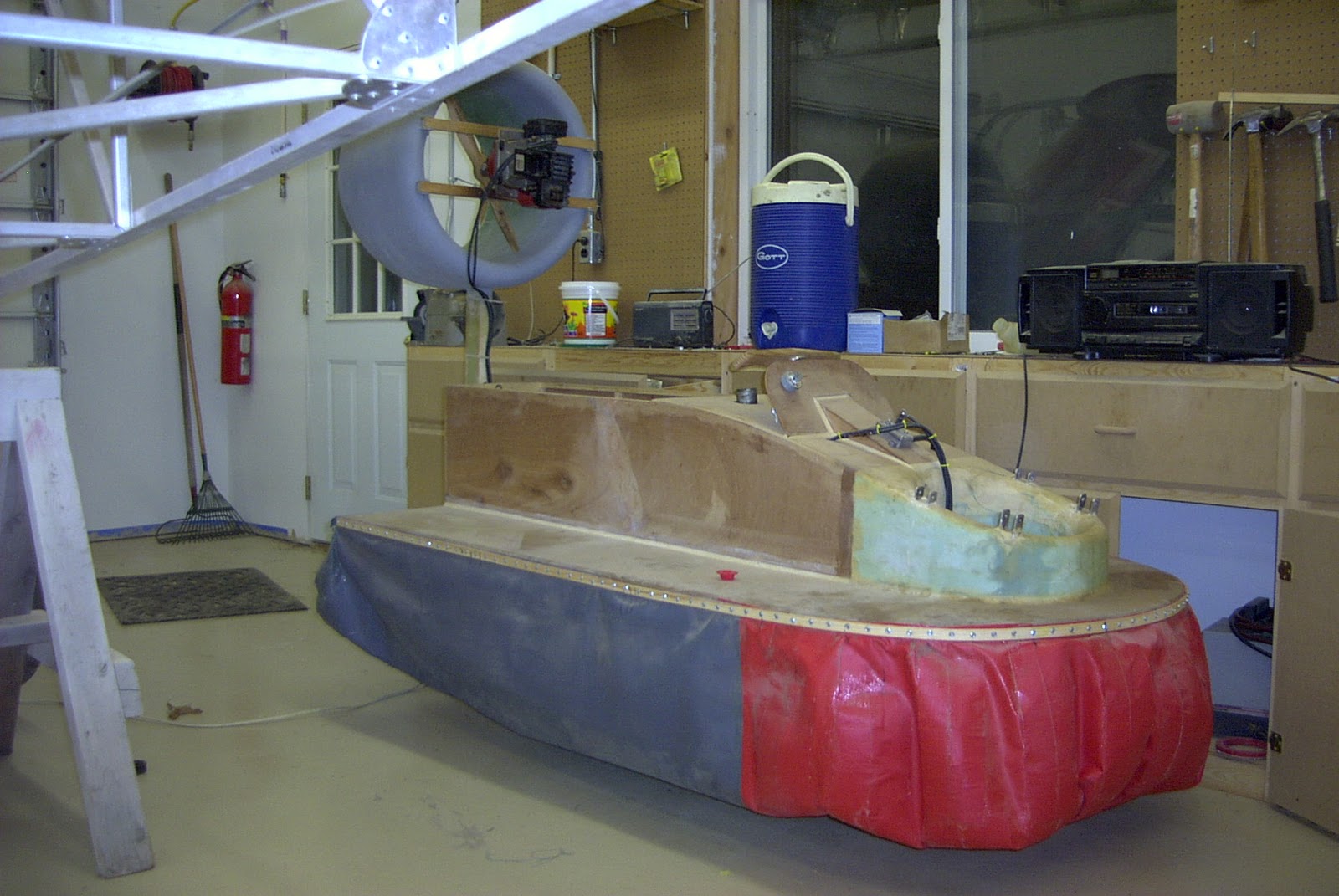
| internal view of the clerestory windows |
The thermal mass is shown opposite of the windows. There where 3 circulation fans. The two end fans were wired to run backwards and the effect was to create two circulation loops. The cement pad was also heavily insulated. It was laid on top of a 4 inch layer of Styrofoam. The footings were also similarly insulated. This had the effect of creating a 12 hour thermal lag. The fans were controlled by a thermostat in the vent area. In the middle of the winter with an outside temp of 10 degrees, the upper vent area could be over 130 degrees. This heat was then flowed down to the lower level and pad by the fans. the other huge advantage of this set up was diffuse lighting. It was a wonderful place to putter around.
 |
| table saw in the foreground with a Tequila Sunrise |
This is a view of the back wall. There was a library style rolling ladder that stowed against the wall on the right. All of my raw stock storage was up on the second level. The lower level had a full bath with tub and shower on the far left. The center was my office and on the far right was the equipment room that had the furnace and the compressor. my friend Kevin and myself actually wired this whole shop in one week end. Kevin is a Master electrician and is a real whiz at laying out conduit pipe. The cooling scheme for the summer involved two 2300 cfm fans located on the roof in the Clerestory space. These fans were also thermostatically controlled . The fans has a modified gravity louver system. When the fans were turned i=on, low pressure would open the louvers which were sitting horizontal. The louvers were required because without them, the hot air in the winter would flow out the top and cool air would flow in from two lower louvers and replace the air. Because of the 12 hour thermal lag on the floor pad, I would turn on the fans in the evening when the outside temp was lower than the inside. The pad would give up all of its heat and in the morning it would serve to keep the lower air cool. Any hot air generated in the day, would accumulate in the upper Clerestory. It would be expelled again later in the day starting the cycle all over again.
This is the 2nd of three very large shops I have owned. Building a shop has been the best investment I have ever made. I have calculated that I got back $1.75 for every dollar I ever spent. In the case of my shop in Wichita, I sold the house in 7 days because of the shop. The same thing happened with this shop in Holland. I really hated to leave this house, shop and city of Holland Michigan. But I could see what was coming to Michigan and the auto industry. I sold this house because of this shop, The Realtor put an ad in the MLS listing calling this shop the Garage-ma-hal. I sold the place in 6 days, this at a time when houses were sitting on the market up to one year. Six months later, you couldn't give a house way in Holland.
Jamies Hover Craft
One day my daughter Jamie was out in the shop working with me and said to me, "Bubby, will you make me something that will go" I looked around the shop and I saw that I had some salvages engines, so I decided to make her a Hovercraft. I had never designed a hovercraft, so I started doing a little reading. I found tat all Hover Crafts develop between .08 and 2 PSI of skirt pressure. Well based on the lower number and the estimated weight of the hovercraft and the current weight of my Daughter, I sized the plan view area . In retrospect, I should have almost doubled that number so she could have enjoyed it as she got older. I considered not feeding her, but my wife put a stop to that!.
 |
| Original concept |
So initially I thought I could power the lift fan with a spare weed wacker engine. This turned out to be a bust. The issue was not a lack of power, but one of fan efficiency. The skirt material by the way, was given to me by a sign shop. I got the last 6 feet on two rolls. This is a vinyl canopy material. So that is what the Hover Craft looked like with the original weed wacker lift engine. As you can see the construction was 1/4" door plywood and Styrofoam covered with fiberglass. The thrust engine was mounted on a swivelling duct. The duct could traverse 180 degrees. There was very little thrust, but that WAS by design, I didn't want Jamie to get away from me.

The final design. I ended up using mu Mothers old lawn mower engine for the lift motor. These following pictures were taken at Johnson Controls in Holland Michigan during Family day. JCI is a fantastic place to work if you are ever fortunate enough to be asked. They encouraged design and were always supportive when it came to projects like this. The Hovercraft was actually put on display in the JCI main design studio for a month. That's quite an honor because of all of the high profile people who saw it.

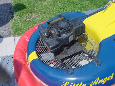
See the black streak to the left of the fan blade in the duct? That was caused by the blare slightly stretching under centrifugal force and rubbing the side wall of the duct. When I first started this engine/fan combination, the Hover Craft skirt would not inflate and surprisingly, when I put my head over the top of the engine, I was being blown by a strong blast of air. It was leaking past the tip of the lift fan. I pulled the plug out of the engine and attached a Bondo plastic squeegee to the end of the blade. I mixed some Bondo and squeegeed it into place by rotating the fan. I kept building it up until I has zero gap. That did the trick and it would hover. When the skirt is fully inflated there is a gap of about 1/2" between the skirt and the ground. It is essentially fiction free.
 |
| Thrust duct |
I used a Homelite Weedwacker motor for the thrust fan, i bought a model airplane prop as the propeller. That was not an optimum choice. later a carved my own prop and doubled the static thrust. The duct was made by first building a sandwich beam of plywood and 2" Styrofoam. The beam is similar to a DC-10 Engine beam, being circular in shape. It looks like a Lollipop. On the front and rear of the circular beam, I glued some 1 lb density floral foam. See the section on the tip mold technique on page 1 for the forming technique. The whole duct was covered in lightweight fiberglass and filled with bondo and sanded.

The duct was controlled by a snowmobile style tiller bar, the internal cable ratio's were such that from lock to lock, the duct could rotate 180 degrees.
This is one of my favorite Pictures of Jamie on her Hovercraft. The thrust wasn't really adequate to push the Hover Craft, most of the thrust was spent on anti torque. In the back of the JCI parking lot, there was a huge open lot that was never completed. It didn't have any lights or parking curbs, just one centrally located storm drain. It sort of looked like one of those dishes you see at the mall for charity donations of your change. The ones where you put a coin in and it spins round and round until it drops in the center hole. that's what we used to do with the Hover Craft, I could put a full tank of fuel in her, start the engines and give Jamie a small push, she would go rounds and round until the fuel ran out.

The other great fun we had together was using it as a merry go round on our Cul-de-sac. I have to tell you once she got moving a bit, the model airplane prop would "Bite" and it was really hard to hold her back.

Jamie eventually outgrew her Hover Craft, but I found another use for it. When we first moved to Texas, Jamie was in the 2nd grade, I went to her school on Science day and gave a demonstration for the kids in her grade. That led to call after call from the other schools in the district and just about every other Friday I was taking the Hover Craft to a school. One day I got my dates mixed up and realized I was going to be late to a demonstration, I called my Wife Terri and asked her to drive the Truck and trailer over to the school. Meanwhile I hauled butt in my old 76 280Z. I actually hit 130 MPH down a country back road. when I got near the school in Midlothian, I was slowed down to about 10 over when a Midlothian cop pulled me over. In his best Texas drawl he asked me "why I was in such an all fire hurry" I told him I was a guest speaker at the school just up the street and I was going to be late. He asked me if I was the "Hovercraft guy" I told him yep, that's me! He said well what in the Hell are you waiting for, lets go!! my son has been talking about you for a week!!! He gave me an escort with siren and light flashing. To this day, I still haven had a ticket in Midlothian! LOL!!
The Zip Drive
Johnson Controls Holland was once owned by Ed Prince, the father of Eric Prince the owner of Blackwater!! Ed Prince from all accounts was one hell of a guy to work for. People would put in enormous amounts of free time to help make programs and projects successful, and this was because at the end of the day, Ed Prince took care of you. Prince Automotive valued original design, they not only encouraged out of the box brainstorming, but every year they had a contest that was mandatory for all designers to enter. They called it the Rube Goldberg contest. I was hired By JCI as an automotive interior designer. i parlayed some Aircraft interior design experience at Hexcel Composites. I was initially hired for the Jeep Commander program. This beast was about 10% larger that a Suburban. It was cancelled 1 week after they hired me. My boss Jeff Gras told me not to worry, I would be reassigned, but meanwhile he said my only job was to win the rube Goldberg contest. What a great job!!!!!
The contest for that year was to make the fastest pinewood derby car. They gave everybody a standard pinewood derby car kit and a bag of loose parts and a $25 Visa Card. You could only spend 25 bucks and there was a weight restriction. No gas motors were allowed. The race would be run on a Cub Scout pinewood derby track and the only rule was that you could not hook to the track and had to be able to sit at the gate. I decided to take the block of wood in the car kit and saw it up on the band saw to 3/16" square strips. I then built up a top fuel dragster truss chassis with the wood. There was a valve spring in the bag of parts and I figured it had the most potential energy. Somehow I had to figure out how to use that spring. I hit on the idea of having a lever arm cock the spring and compress it. The arm was designed to go "Over Center" so that when fully cocked, the spring pressure actually held it shut. To pull the arm past center I used 4 rubber bands in the bag of parts. I spent the 25 bucks on precision instrument ball bearings. My team partner was Peggy Gustafson a very talented model builder who was also recently assigned to the commander Program. Peggy is an excellent craftsman and together we built the Zip Drive. I called it the Zip drive after a product made by Iomega, a stock I had an investment in at the time.
 |
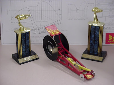
| The Zip Drive |
The only parts not in the parts bag were the CD discs, but since we didn't have to pay for them it was allowed. The lever arm attached to a variable ration capstan that Peggy made out of aluminum It was pressed to the rear axle. A piece of string wrapped over this capstan and attached to the yellow lever arm.
 |
| top view of the Zip Drive |
The valve spring is shown in this view as is the rubber bands. The tuning involved finding the correct position of the rubber band attachment so the right amount of starting torque was applied to the rear wheels. Too much torque and she would do a burn out, not enough and the arm couldn't past "center" the wheels were also wrapped with a rubber band to provide a traction surface
 |
| Side view of the Zip Drive |
there was a small brass tube pressed into the frame that allowed the arm to pivot. We used an axle from the pine wood kit as a pivot. This axle could be easily removed so we could change configurations.
The race was run as a 4 heat elimination. There were about 150 entries. We were placed in the middle of the pack. Most of the cars were gravity powered and a few were powered. None however could figure out how to use the valve spring. Most of the gravity cares were running about 6 seconds. The powered ones were hitting the high 4's Our design used the rubber bands to pull the main arm over center and launch the car. Once we were about 3 feet in front of the gate, the arm went over center and the main power was hooked up to the rear wheels. The drive was designed to accelerate right up to the finish line. We crossed the line and buried in the catch box a full 4 seconds before the nearest car. We killed everyone!!
 |
| And the Winner is........... |
JCI encouraged charity, its part of the Dutch heritage of western Michiganders. As such all voting was accomplished by putting a dollar in a can next to the car. The Zip Drive not only came in first with a run of 2.3 seconds down a 50 foot track, but also was voted the best design. She earned $2300 for charity. I was very proud of this for my first project in the auto business. There would be other Rube contests and in one I would win the engineering award, but none was as much fun as this one. Especially gratifying was working with the highly talented Peggy Gustafson.
The Miss Mary Kate
This is a Hydroplane project I finished. A friend of mine in Holland Michigan, Scotty Hansen, gave me a partially completed Hydro project. I decided to complete it and give it to my Nephew Andy for his 10th Birthday. Andy lives on a lake in eastern Michigan in the northern Detroit suburbs. He lived with his Father Aaron and my sister Mary Kathleen (Thus the name Miss Mary Kate!!) The basic construction was 1/4" fir plywood. My final contribution was to complete the upper deck and the shovel nose rub rail. That was an interesting process. it required that I steam a piece of 2" x 2"X 10' Oak rail.

I made a steam pot out of a 2" pipe. I filled it with water and then build 3 camp fires under it. It steamed the wood so well, I could have tied the board in a knot. The final touch for the Hydro was the addition of a rear wing. It has absoluly no meaning or use, other than to look cool.

The final finish was a thin layer of fiberglass follwed by days of filling and sanding automotive bondo. I used an old 7 hp fishing boat motor and wth my nephew in the boat, it would easily get up on the two sponsons and plane. Top speed was about 30 mph.


 The duct was controlled by a snowmobile style tiller bar, the internal cable ratio's were such that from lock to lock, the duct could rotate 180 degrees.
 The other great fun we had together was using it as a merry go round on our Cul-de-sac. I have to tell you once she got moving a bit, the model airplane prop would "Bite" and it was really hard to hold her back.


 I made a steam pot out of a 2" pipe. I filled it with water and then build 3 camp fires under it. It steamed the wood so well, I could have tied the board in a knot. The final touch for the Hydro was the addition of a rear wing. It has absoluly no meaning or use, other than to look cool.