Welcome to my Robin Blog.

It was suggested to me that I start a Blog on my ultralight project the "Robin". I have been working on this project for 4 years. On one of my first days at Vought aircraft, a stress man and future friend named Kenny Andersen walked up to me and said, "Aren't you the Mark Calder that designed the Wren Ultralight" Why yes I am I said. "well what have you done lately?" That was the genesis of the Robin design. The first 2.5 have been spent in the design phase. Actual construction started 1.5 years ago and has actually progressed smoothly. There have been a number of changes from the onset, but for the most part it is following my original concept. I will eventually sell plans for the Robin and make available all molded parts, fittings and welded assemblies. The Robin is designed to FAA part 103 and as such requires no pilots license to fly, although I think its a good idea to actually learn how to fly!! The actual name "Robin" was my Daughter Jamie's idea, I asked her to name the design based on my "cute little bird" theme (Wren)


Every good aircraft design has a "Mission" in mind before the actual design is started. A good designer will refer back to this mission every time a design decision must be made. Good design after all is just a series of good design decisions. On my first Ultralight design the Wren, the mission was to design a high performance low powered aircraft. The reduction of drag was the prime concern. I had been flying powered Hang gliders prior to this and because of this experience, I placed a high priority on climb performance. While most designers chose bigger engines, I chose lower drag and high aspect ratio (low span loading) wings. The Wren could out climb conventional Ultralight with up to 65 hp. The Robin follows this philosophy, but tries to improve on the performance of the Wren. Ultralight are not built by "rich" people, they offer an inexpensive means to enjoy one of the greatest experiences of my life, low speed soaring and flying.


Design Concept


The cost of an aircraft is directly proportional to its weight. , if low drag can be achieved then lighter and cheaper engines can be used. The Robin expands on the design mission of the Wren by using a longer span (40') wing and using a low speed laminar flow airfoil, (Wortmann FX 170) The leading edge of the wing on the prototype is molded fiber glass. The spar has been placed at 33% of the wing chord because the chosen airfoil is laminar over the first 32%. The aft covering is light weight Dacron Fabric. The leading edge of this fabric is purposely pinked and placed at the 32% chord point to facilitate laminar transition and elimination of separation bubbles. The main difference between the original design of the Robin and the current final design is the elimination of the single mono wheel retractable landing gear. Part 103 does not allow for a retractable landing gear. Which is really unfortunate because I spent a long time designing a really neat mechanism!!

In the course of the 4 years I have worked on the Robin, the structural design concept has evolved radically. Originally I was going to draw on the design of the Wren and use essential the same construction concepts. The original design of the Wren was heavily influenced by my Friend Steve Wood's Sky Pup design. I lived in Wichita Kansas and worked at Cessna Aircraft along with Steve. I watched his progress on the Pup and was very impressed with his concepts. I adapted the concept of using Styrofoam sheeting as the shear panels for the fuselage and the wing ribs. I did not however use the foam for the shear webs of the wing as Steve did. I originally wanted to build the fuselage of the Robin in a similar manner. Weight and the desire to not use foam for the basic structure due to the danger of fuel leaking eventually drove me to a all wood fuselage design. The wings were designed to take advantage of the Graphlite carbon pultruded material pioneered for the experimental aircraft by Jim Marske. I was familiar with this product from my experience at Bell Helicopter where it was considered in the construction of the V-22 wing.


2 stroke exhaust design and build

The stock muffler that came with my MZ 34 was not suitable for my design. Besides being  the wrong configuration, it weighed 4.8 lbs and was not tuned. I talked to Leon Massa of Compact Radial engines and he told me that the design is conservative and not designed to any specific power band. Due to the configuration I chose for the Robin, the exhaust must exit the engine and turn 90 degrees aft.  I am emulating the cheek cowls of the original Fournier RF4D which was powered by a Limbach VW conversion. That engine is a flat 4 cylinder.  Its ironic, but a single cylinder 2 stroke engine is actually wider than it is tall. I do not like the ultralight designs that have the pipe just hanging in the breeze. I wanted to design the cheek cowls such that it would streamline the carburetor and air filter and the the exhaust. I plan on ducting the cooling air into the L/H cowl and flow it over the head and then let it exit out the R/H cowl. Because of this, the cowls will be slightly asymmetric.  Another side benefit is that the cheek cowl will act as a secondary sound barrier for the case borne noise of the exhaust. Most sound from a two stroke engine originates from the exhaust. This is one of the reasons why its desirable to have a completely round cross section. This eliminates flat areas that will resonate and crack. Cracking is a huge concern on this pipe, because of this I am using the original spring suspension and I have incorporated two small rubber shock mounts. The exhaust will have a large freedom of movement to allow it to move with the engine during idle. 
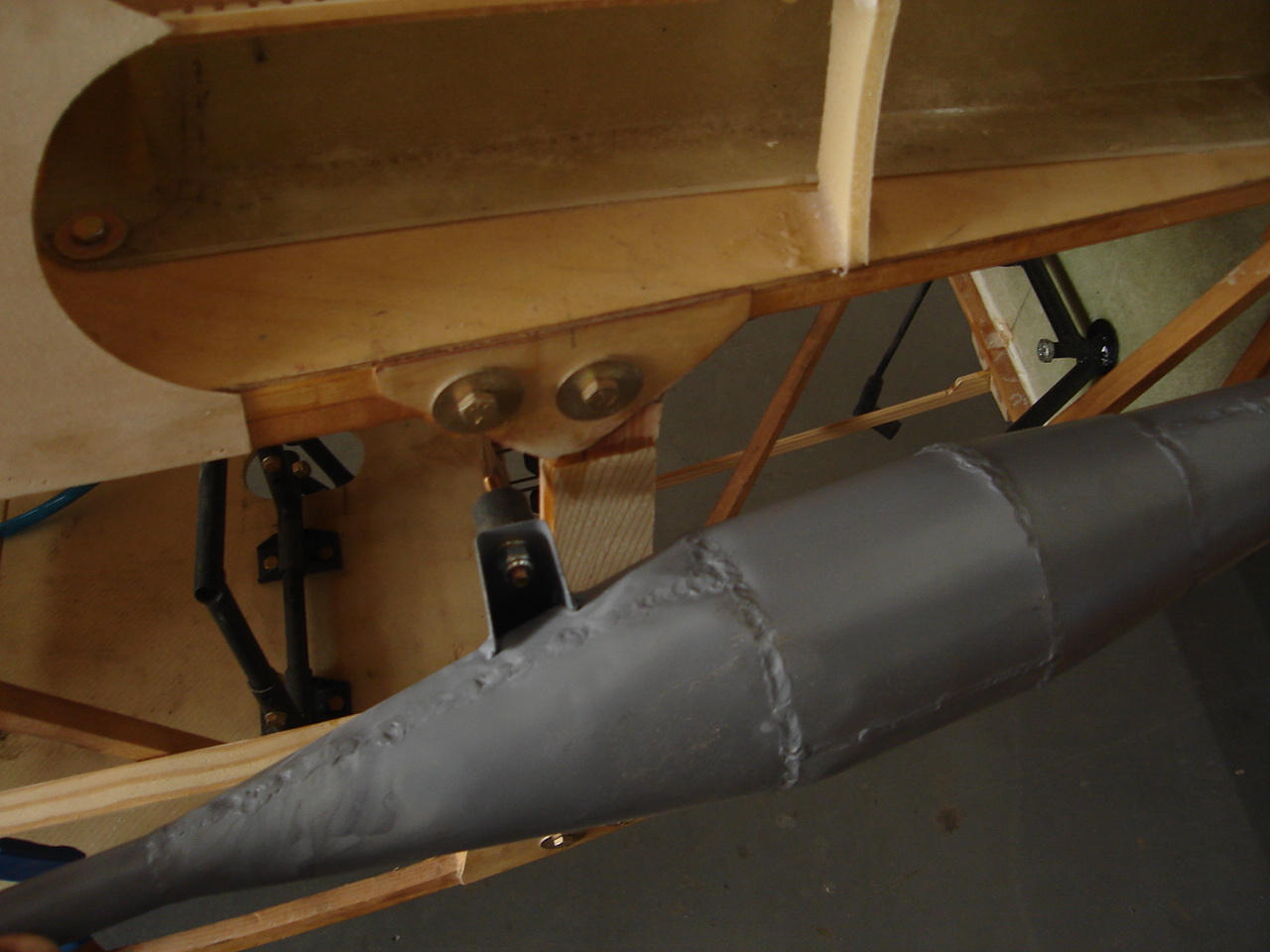
pipe shown in mounting position


I had my first introduction to the benefits of a tuned exhaust with the first prototype of my Wren. I flew the original prototype with a 22HP Xenoah engine. All I had for an exhaust was a short length of flex tubing. The prototype in this configuration was terribly underpowered. One day I was flying south east of Wichita near Rose Hill. I was flying parallel to some huge power lines when the engine started to sputter.  I had no choice but to turn away from the lines and set down in a freshly cut wheat field.  As I was rolling out on landing a young kid on a 2 stroke motor cross bike came out to meet me. I immediately apologized for landing in his field. He told me that he thought I saw him wave to me and motion me to land? I again apologized and said I hadn't. He said he wanted to meet me and tell me that my engine was running really rich and was "4 stroking" as it ran. He then proceeded to tell me that I needed a tuned pipe really bad. I looked at his bike and it was obvious he had made the pipe for that bike. I asked him if he knew how to make a tuned pipe? "Of course" he said. We rolled the Wren into his dad's barn and set about designing a tuned pipe. We had to partially disassemble the engine to determine the timing of the intake and exhaust ports. He set up a degree wheel on the crank and we recorded the exact point the exhaust port and intake port opened and closed. The timing and design of the pipe starts from the point the exhaust port opens. Here is a picture of what my new pipe looks like. 
straight pipe before elbow was added
                                                                       A modern tuned pipe consists of an expanding section, a constant section and a diffuser or tapering section. The final section is an outlet stinger pipe. The process starts with the exhaust pulse, it is quite powerful and travels approximately at the speed of sound. All of the pipe section geometry are based on the speed of sound and the time it takes a wave  to travel . As the first pulse leaves the exhaust port and travels down the first expanding section, the piston continues its downward power stroke, When the original pulse reaches the end of the first tapered section, an inverted negative pressure wave is created. This wave in turn travels back up the first expanding section and as it does it increases in intensity due to the constriction of the tapered section. This negative pressure pulse arrives back at the exhaust port at the exact time that the intake port opens. This negative pulse has a scavenging effect that serves to draw in a new fresh air-fuel charge. This pulse is so strong that it actually pulls the fresh charge out of the cylinder and into the expanded exhaust section. Meanwhile the original power pulse has traveled the length of the constant section and has arrived at the diffuser section. This has the effect of creating a very strong positive wave that again travels back up the exhaust toward the exhaust port. It arrives and actually pushes the fresh fuel air charge back into the combustion chamber. By this time the piston has traveled to the point where the intake port is closed. This ramming of the charge back into the combustion chamber has the effect of effectively increasing the compression ratio and increasing horsepower. Not only is horsepower increased, but fuel economy is greatly improved. My young friend calculated all of these dimensions from a set of formulas he got from a book on 2 stroke tuning. You could do that or go to the web site
    http://www.buildandclick.com/    and order the design software . There is also a useful freeware sight he links to that will lay out the conic sections. My first attempt for the Robin is a bit crude, but I am sure I will be building a second one before its all finished. Once I have the values of the tapered sections I will have a professional builder make the pipes for future builders. The new pipe by the way weighs 1.8 lbs.


That young man in my story actually became my exhaust supplier for the production of my Wren. I eventually introduced him to other manufactures and for many years he was building custom pipes for a bunch of ultralight manufactures. When we finished the pipe for the prototype and I took off, it was like I had a brand new engine. The rate of climb easily doubled and I now felt I was flying a far safer ultralight. The "Four stroking" condition stopped and my plugs never fouled again.

I was looking at the stats for this blog and I am absolutely amazed at the international spread of this blog. I want to say hello to all of the Russians , Canadians, Germans, Kiwi's and Aussies who seem to be pretty good fans. I also want to thank Gordon from the Yahoo Wooden airplane group. I took your comment to heart about making things seem tougher than they should be. You are right, I am. I guess this is mostly due to frustration of working professionally for a major airframe manufacturer. These days there is a real absence of design in my field, the industry is so taken with cost cutting that the least amount of time in a schedule is now the engineering. Unfortunately it really shows too.  The biggest problem I have when I design home built projects is I tend complicate things because I can!!! That is to say, I have studied the way the big boys do things and I am always trying to introduce some level sophistication to the process, the end result is usually complicated and heavier. My old mentor the late John Kaufman of Wichita Ks, tried to instill the KISS principal in me when ever he reviewed my designs. I try to keep him in mind when ever I design something. Consequently, my prototypes have all been a bit over designed. I usually get it right on the second try however!! Currently I am being greatly influenced by one of the most beautiful designs I have ever seen, the ASW 20 sailplane. I am redesigning my wing and the attach system to a similar configuration. The horizontal attach is also being redesigned to simplify the breakdown process. I saw a pretty slick automatic aileron disconnect on the outboard wing of a Grumman Tracker and a similar design on the prototype of the Stits Playboy at the Lakeland Museum in Florida. I plan on incorporating this feature into the final design.  I was just down at Lakeland a week before the airshow. I have to say that that show was the finest I never attended!! My goal all along was to have the prototype at that airshow, my frequent trips to Israel however has delayed my progress. Thankfully, in this case I was late!! It looks like every single ultralight on the flight line was destroyed.

No comments: