Welcome to my Robin Blog.

It was suggested to me that I start a Blog on my ultralight project the "Robin". I have been working on this project for 4 years. On one of my first days at Vought aircraft, a stress man and future friend named Kenny Andersen walked up to me and said, "Aren't you the Mark Calder that designed the Wren Ultralight" Why yes I am I said. "well what have you done lately?" That was the genesis of the Robin design. The first 2.5 have been spent in the design phase. Actual construction started 1.5 years ago and has actually progressed smoothly. There have been a number of changes from the onset, but for the most part it is following my original concept. I will eventually sell plans for the Robin and make available all molded parts, fittings and welded assemblies. The Robin is designed to FAA part 103 and as such requires no pilots license to fly, although I think its a good idea to actually learn how to fly!! The actual name "Robin" was my Daughter Jamie's idea, I asked her to name the design based on my "cute little bird" theme (Wren)


Every good aircraft design has a "Mission" in mind before the actual design is started. A good designer will refer back to this mission every time a design decision must be made. Good design after all is just a series of good design decisions. On my first Ultralight design the Wren, the mission was to design a high performance low powered aircraft. The reduction of drag was the prime concern. I had been flying powered Hang gliders prior to this and because of this experience, I placed a high priority on climb performance. While most designers chose bigger engines, I chose lower drag and high aspect ratio (low span loading) wings. The Wren could out climb conventional Ultralight with up to 65 hp. The Robin follows this philosophy, but tries to improve on the performance of the Wren. Ultralight are not built by "rich" people, they offer an inexpensive means to enjoy one of the greatest experiences of my life, low speed soaring and flying.


Design Concept


The cost of an aircraft is directly proportional to its weight. , if low drag can be achieved then lighter and cheaper engines can be used. The Robin expands on the design mission of the Wren by using a longer span (40') wing and using a low speed laminar flow airfoil, (Wortmann FX 170) The leading edge of the wing on the prototype is molded fiber glass. The spar has been placed at 33% of the wing chord because the chosen airfoil is laminar over the first 32%. The aft covering is light weight Dacron Fabric. The leading edge of this fabric is purposely pinked and placed at the 32% chord point to facilitate laminar transition and elimination of separation bubbles. The main difference between the original design of the Robin and the current final design is the elimination of the single mono wheel retractable landing gear. Part 103 does not allow for a retractable landing gear. Which is really unfortunate because I spent a long time designing a really neat mechanism!!

In the course of the 4 years I have worked on the Robin, the structural design concept has evolved radically. Originally I was going to draw on the design of the Wren and use essential the same construction concepts. The original design of the Wren was heavily influenced by my Friend Steve Wood's Sky Pup design. I lived in Wichita Kansas and worked at Cessna Aircraft along with Steve. I watched his progress on the Pup and was very impressed with his concepts. I adapted the concept of using Styrofoam sheeting as the shear panels for the fuselage and the wing ribs. I did not however use the foam for the shear webs of the wing as Steve did. I originally wanted to build the fuselage of the Robin in a similar manner. Weight and the desire to not use foam for the basic structure due to the danger of fuel leaking eventually drove me to a all wood fuselage design. The wings were designed to take advantage of the Graphlite carbon pultruded material pioneered for the experimental aircraft by Jim Marske. I was familiar with this product from my experience at Bell Helicopter where it was considered in the construction of the V-22 wing.


WingPanel Test


Test set up with members of the "Brain Trust"
Early on in the project I decided to test to destruction a full size wing panel. This was a tough decision because of the cost and time required to do this. But as it turns out,  this was indeed a fortunate decision. The test set up consisted of a strong back constructed from steel square stock and I-beams bedded into two 3 foot holes drilled into the limestone that makes up my part of Texas.  I was fortunate enough to be able to draw on the local “Brain Trust” from Vought Aircraft, Bell Helicopter, Lockheed Martin and American Eurocopter. All fellow designers and stress engineers and most importantly, friends in the business. I learned a long time ago on my Wren project that it pays to have a second set of eyes available.
Test set up showing nose angle

The wing panel itself was mounted inverted with the nose angled downward at 14 degrees. This is to simulate the abrupt pull up condition at the max maneuvering speed. This will induce the leading edge compression load that will verify the leading edge spar and the fitting.

The actual load was 90 lb bags of ready mix concrete. Fortunately a neighbor was just starting a fence project and was gracious enough to let me “borrow” them for a day. The load schedule was designed to emulate the constant loading of a rectangular “Hershey bar” wing with the parabolic drop off that occurs near the tip. The bags were to be placed in 1”g” increments. The design criteria I established was to have no skin wrinkling less than 2.5 “g” because I am trying to maintain laminar flow. After the first “g” of load was placed, it was realized that this wing would have too much deflection. It was decided to continue the testing to see where the weak link was in the design.


At appox. 3.5 “g” the deflection was 21 inches at the tip . When we attempted to add the next “g” load, it was noticed that there was severe web buckling between the main shear pins. This area of the wing used a box spar with a 1 inch foam core. The bond had failed obviously between the main web and the foam. A complete shear failure occurred shortly after the buckling was noticed and the wing broke. 
Shear web failure caused by web instability
Investigation of the foam bond joint revealed that there was never a complete bond to begin with. I built this portion of the spar on a very hot day and due to the insulating properties of the foam, the epoxy and micro balloon mixture had an exothermic reaction and never bonded to the web. I realized that this could easily happed to any builder so I immediately revised my design to eliminate the foam box design and use bonded vertical stiffeners instead. I found a product used in the electric motor business called NEMA grade C fiberglass insulation. This is a fiberglass sheet product made from 120 style glass and polyimide epoxy resin.. Its produced in an autoclave and is rated to 450 degrees working temp. Besides being a high quality laminate and product, its also cheap and available in numerous thicknesses. I was using ¼” thick plates as the main intercostals at the shear pins. I used .063” thick plates for the vertical stiffeners.
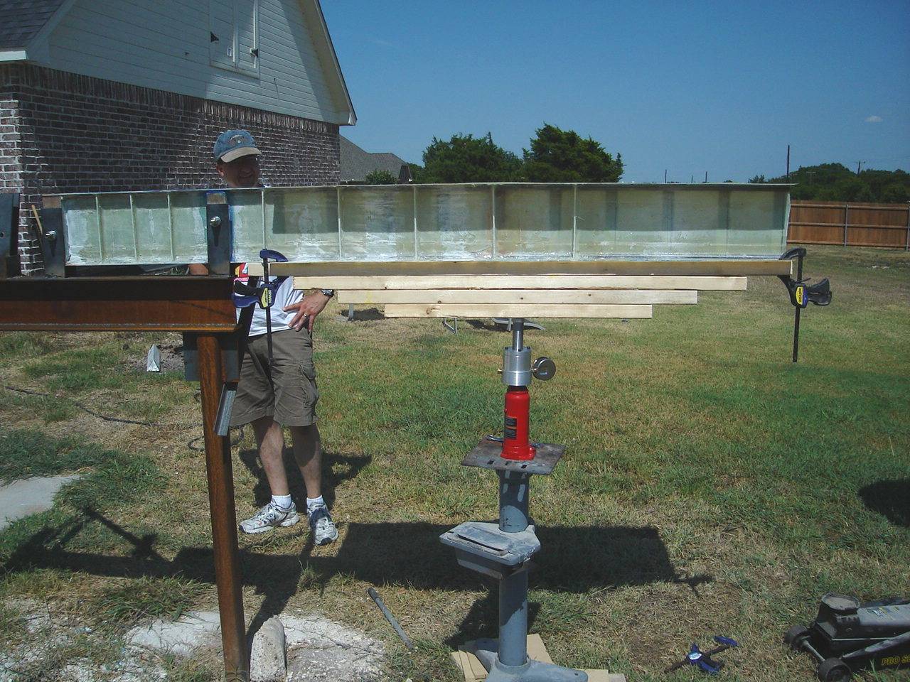
I decided to retest the wing to verify the new stiffeners and to verify the shear capability of the root web. The wing spar shear web lay up schedule is constant out to wing station 36, because of this I cut off the damaged inboard section of the spar and rebuilt the outboard 18 inches of the spar by adding a new shear pin intercostal. The outboard section of the wing was damaged when the spar struck the ground so that portion was cut off and discarded. I bonded a wooden plate to the outboard section of the undamaged spar so that I could gain enough leverage to emulate the design bending moment at the new “root” It was decided to test the spar in the up right position. Load was applied with a floor jack through a load cell I designed. The cell consisted of a hydraulic piston with exactly one square inch of area. Automatic transmission oil was pressurized and the pressure read by a hydraulic pressure gauge. The readout was one for one. The cell was calibrated at a local truck weigh station.
Testing verified that the shear web was fully stable at the design ultimate load of 1325 lbs. The final design of the prototype wing incorporated bonded vertical stiffeners and roughly double the amount of graphite used in the test spar.


No comments: