Welcome to my Robin Blog.

It was suggested to me that I start a Blog on my ultralight project the "Robin". I have been working on this project for 4 years. On one of my first days at Vought aircraft, a stress man and future friend named Kenny Andersen walked up to me and said, "Aren't you the Mark Calder that designed the Wren Ultralight" Why yes I am I said. "well what have you done lately?" That was the genesis of the Robin design. The first 2.5 have been spent in the design phase. Actual construction started 1.5 years ago and has actually progressed smoothly. There have been a number of changes from the onset, but for the most part it is following my original concept. I will eventually sell plans for the Robin and make available all molded parts, fittings and welded assemblies. The Robin is designed to FAA part 103 and as such requires no pilots license to fly, although I think its a good idea to actually learn how to fly!! The actual name "Robin" was my Daughter Jamie's idea, I asked her to name the design based on my "cute little bird" theme (Wren)


Every good aircraft design has a "Mission" in mind before the actual design is started. A good designer will refer back to this mission every time a design decision must be made. Good design after all is just a series of good design decisions. On my first Ultralight design the Wren, the mission was to design a high performance low powered aircraft. The reduction of drag was the prime concern. I had been flying powered Hang gliders prior to this and because of this experience, I placed a high priority on climb performance. While most designers chose bigger engines, I chose lower drag and high aspect ratio (low span loading) wings. The Wren could out climb conventional Ultralight with up to 65 hp. The Robin follows this philosophy, but tries to improve on the performance of the Wren. Ultralight are not built by "rich" people, they offer an inexpensive means to enjoy one of the greatest experiences of my life, low speed soaring and flying.


Design Concept


The cost of an aircraft is directly proportional to its weight. , if low drag can be achieved then lighter and cheaper engines can be used. The Robin expands on the design mission of the Wren by using a longer span (40') wing and using a low speed laminar flow airfoil, (Wortmann FX 170) The leading edge of the wing on the prototype is molded fiber glass. The spar has been placed at 33% of the wing chord because the chosen airfoil is laminar over the first 32%. The aft covering is light weight Dacron Fabric. The leading edge of this fabric is purposely pinked and placed at the 32% chord point to facilitate laminar transition and elimination of separation bubbles. The main difference between the original design of the Robin and the current final design is the elimination of the single mono wheel retractable landing gear. Part 103 does not allow for a retractable landing gear. Which is really unfortunate because I spent a long time designing a really neat mechanism!!

In the course of the 4 years I have worked on the Robin, the structural design concept has evolved radically. Originally I was going to draw on the design of the Wren and use essential the same construction concepts. The original design of the Wren was heavily influenced by my Friend Steve Wood's Sky Pup design. I lived in Wichita Kansas and worked at Cessna Aircraft along with Steve. I watched his progress on the Pup and was very impressed with his concepts. I adapted the concept of using Styrofoam sheeting as the shear panels for the fuselage and the wing ribs. I did not however use the foam for the shear webs of the wing as Steve did. I originally wanted to build the fuselage of the Robin in a similar manner. Weight and the desire to not use foam for the basic structure due to the danger of fuel leaking eventually drove me to a all wood fuselage design. The wings were designed to take advantage of the Graphlite carbon pultruded material pioneered for the experimental aircraft by Jim Marske. I was familiar with this product from my experience at Bell Helicopter where it was considered in the construction of the V-22 wing.


Sensor wiring and routing

 I woke up yesterday and checked the stats on this blog, and it was thru the roof!! All thanks to my fellow EAA members logging in. It seems the EAA light sport magazine published a link to the EAA thread I started on the Robin.   Welcome all my EAA friends!!

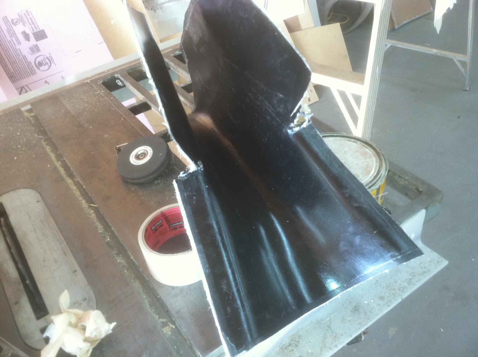
I am currently waiting for my friend Ed  http://mmwauto.com/index.php/services.html to finish painting the horizontal/Vertical fin fairing , the canopy Yarmulke and the tip caps for the vert fin and rudder.Meanwhile I started installation of the engine wiring and instrumentation. I bought a set of all electronic gauges from Jim Weibe http://www.beliteaircraft.com/  I was particularly interested in his electronic fuel gauge. Its unfortunate that I did not plan for these gauges from the beginning. I could have incorporated a flat section into the fuel tank that would have accepted the sender. However, the method I came up should work just fine. The fuel sensor appears to be a variable capacitance sender. There is a outer tube that acts as one plate and a center 14 gauge wire that acts as the other plate. As the fuel enters this tube, the fuel will act as a variable dielectric and upset the balance of a capacitance bridge. The difference is read on the fuel gauge. There are two standard lengths of the senders, 12 and 24 inches. You can trim the probe to any length you need. The base of the probe mounts to a 3/16" thick plate that is drilled and tapped. To lessen the weight and add additional bond area, I drilled lightening holes between the threaded holes. I countersunk both faces so Flox, which will be forced through, will act as a positive lock. I started the process by filling the  threaded holes with carnuba wax. I coated the fasteners with carnuba and inserted them into the plate. I sanded the bond surface with 100 grit paper and then wiped the bond surface with MEK. This is then carefully set aside and not allowed to come into contact with any contaminants.

Fuel level sender base
This looks like a real mess, but after it cures, the mating surface will be ground clean and flat. a flox radius was swept all around the perimeter and inside. This serves to increase the bond area. One trick I like to use is to add 3M 777 spray into the resin before I mix the flox in. I have found that this dramatically increased the peel strength of the bond. This is a poor mans method of creating a 'Toughened Resin" system The all composite 787 uses a toughened resin system. The idea is to add elastomeric polymers to the resin matrix. The addition of an elastomer or rubber molecule into the matrix, allows the brittle epoxy to have a slight amount of give. Since all bond stresses concentrate on the edges, this additional give keeps the edge from delaminating or peeling away. The effect is dramatic. I used a toughened resin on the wing spar of the Robin and I conducted my own testing . Without the toughener, the peel strength was around 100 psi. With it, 1000 psi, a ten fold increase. Be forewarned, I have not tested this in the hot/wet environment and I understand that there is some degradation. There are commercial tackifiers available that are used in the VARTM industry that not only increase the peel strength, but also increase the hot/wet properties. I installed the cylinder temp sender and the EGT sender. I then routed the engine wiring. On the computer in the evening I will be laying out the pattern for the gauges. I am also looking for a lighter weight throttle quadrant. if I cant find one commercially available. I will design and build my own.
Wires after routing

This shows the sender installation.
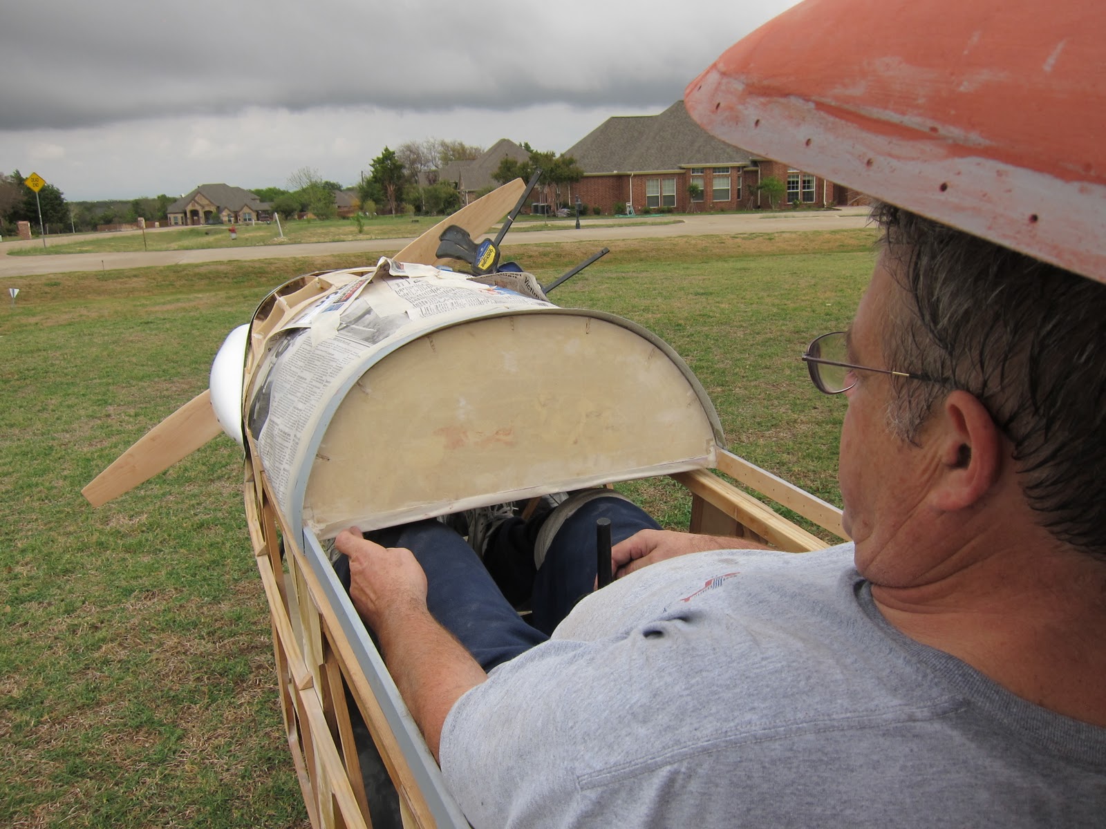
I want to be able to remove the canopy when I am working on the plane and when it is being suspended from the hanger ceiling at my local airport. So that means that all wiring must terminate right at the canopy hinge with a multi pin plug. I am looking for that plug right now. I will need to route a Tygon tube from the wing pitot to the airspeed pressure sensor mounted behind the airspeed gauge. This tube will also have to route to the area of the plug. I need to figure out a quick disconnect not only at the canopy hinge, but at the wing root also.

keyhole slot


I had to add a Keyhole slot at the base of the tank fairing. so it could be removed without disconnecting the wires. I will have to add two more on both ends to accommodate the throttle cable.


Iso view of the engine installation


This shows the additional baffle plate I  added to firewall so I can seal the gap around the cheek cowls. I am using the stock carb. air filter, but I would like to find a more compact unit, as it is now, I have to bend the filter aft inside the cheek cowl. It will work, but I would like to find a better  filter.

So a little searching and some more scrounging and I should have the instruments all installed. It feels good to make final saftied connections. the last job before covering will be to re-rig the wings and mount the ailerons and route the aileron cables. Also today I bought 3 spring scales and I weighed the whole mess!! No estimating, because all of the parts are completed. assuming 18 lbs for complete cover and paint (should be conservative) I weight 243 lbs!!!! That is a huge relief, but this is the reason the prototype has no brakes or starter. however, my initial prop weighs 8 lbs, this will reduce to 1.5 lbs when I finally choose the correct diameter and pitch. I will ask CGS props to carve me a fixed spruce prop. If I  have time I will carve my own. I use the Fred Weick method he outlined in a NACA pub from 1929. Come think of it, I will carve my own and detail it in the blog, its really a very simple process and 90% of the work can be done on a band saw.

Horizontal/Vert fin fairing

One of the last "big" jobs I need to finish is the fairing between the Vert fin and the horizontal. There is a natural gap between these two parts and passing through this space is the elevator. A slot will be cut in the fairing to allow for full up travel of the elevator. Because I cannot make a lightweight "insitu" fairing out of foam, I decided to make a full mold. The fairing will be laid up in this tool with one 3.2 oz fiberglass surface ply and one layer of 8 oz graphite.
Tape being applied to exposed plywood
 The project started by covering all of the exposed plywood with aluminum duct tape. We used to call this 500 mph tape at Cessna, we used it to attach external instrumentation wires on the Citation 3. The white strips on the middle of the Vert fin leading edge are adhesive backed 3" wide 60 grit sand paper. I will uses these to contour the floral foam blocks that are attached later. I have used this technique to make contoured sanding blocks for automotive body repair. If the car I am working on was too severly damaged in this area, I would find an umdamaged car and make contoured sanding blocks out of styrofoam.
1 lb/c ft Floral foam blocks
The area where the fairing is to be built is stuffed with floral foam blocks. Notice how the sand paper has some foam dust on it. The blocks are rough cut using a wood saw and a hacksaw blade. The first contour cut will be the side profile of the fairing. Before starting the foam blocking, I used a piece of welding rod and taped it to the horizontal and the leading edge. I used two pieces of tape on each end so the wire would have an established tangency. The fairing needs to smoothly blend between these surfaces.I made a tracing on a piece of poster board and I will use this as a guide when I cut the side profile.

Foam after contouring
After the side profile was shaped, the foam was sanded to a pleasing shape using another block of foam. Once I was satisfied with the shape, I laid up 2 light weight plys of fiberglass and let everything cure overnight. The next day, I started coating the glass with Bondo. I have gotten pretty good working with Bondo. I attribute this to having grown up in the Detroit area. As a 16 year old driving around, every spring was spent repairing rust from all the salt on the road.
The technique for using Bondo is to lay on multiple thin layers. Sanding in between each coat.
multiple layers of Bondo

36 grit paper on an air powered file board is used to rough contour the bondo. As the shape gets closer, finer and finer sandpaper is used. The last grit will be 180. There is no need at this stage to use any finer. A word about materials here is in order, do not rely on the chain stores (Auto Zone...) for your materials. Find a body shop supply business. They will have the professional grade body fillers and sand paper. The price is always less than the inferior commercial products.
Final Bondo Coat
After you are satisfied with surface and it is wave and pit free, block sand the surface with 220. The next step is to coat the surface with professional grade Spot putty. Spot putty is a lacquer based product that dries by evaporation. The thicker the coat, the longer it takes to dry. Spot putty is not used to contour the surface, its used to fill the sanding marks an very slight depressions.
Spot putty applied


I usually let this dry for 24 hours .


Final sanding after application of Spot Putty

This will give you an idea about how much of the spot putty is left after sanding. The spot putty is first sanded with 220 grit, and finish sanded with 320. at this point I taped up and papered the rest of the plane and applied 5 coats of carnuba mold release paste wax.


PVA Poly vinyl acetate

On top of the polished wax, 6 coats of PVA were sprayed on. The coats were allowed to thoroughly dry between applications. Once the surface has been coated, the PVA forms a film that will act as the release surface


Texas AutoClave
Between coats, I rolled the fuselage out into the "Texas Autoclave".  85 degrees F here today, in the middle of October. Texas is a wonderful place to live 3/4 of the year. True Texans however are solar powered and don't care a whit about the heat of summer, in fact they say its a natural Yankee barrier!! They curse the day Airconditining was invented!!!
Gel Coat being applied

Using my Gel coat gun, I sprayed 1/2 a pint of Gel coat. the gel coat is allowed to cure until tacky and then raw resin is applied over the gel coat and pieces of non directional mat is applied. It took about 2 hours to cure enough so I could pull the mold off.


Fairing Mold
Tomorrow I will lay up the fairing.


Fairing in position


 Finished fairing!!! 1.0 ounces.

The fairing will be bonded to the horizontal

Progress, Squawk list burn down!!

My good friend Mike Lafrance and his wife Audrey flew out from San Diego for the week end. Mike and his Dad Neal are old friends from Wichita. I first met Neal at my first engineering job ever at Boeing Military Aircraft in Wichita Kansas. Neal was a designer on a very cool 'Black" program that eventually was made public and called "Pave Tiger" My involvement was packaging a tuned resonant exhaust chamber. Neal is one of the original founding members of the EAA, he was in the Wisconsin National Guard with Paul Poberezny when the idea for the Experimental Aviation Association was born. Neal has an award winning Wittman tailwind. he also built a Wittman V-Witt racer and actually raced against Steve Wittman in his final race. I owe Neal a great deal for all his support during the design and building of my old Wren and  years later when I had a chance to repay his kindness I volunteered to design and build his cowl on his beautiful Culver STF (Steel Tube Fuselage).
Mike and Neal Flying the Cadet

 His son Mike is also quite an accomplished pilot, home builder and restorer. His Luscombe 8A and his 11A sedan are works of art!! it was sure good of Mike to burn his vacation helping me work on the Robin. The following pictures are a collage of our progress. We completed the rig of the rudder pedals, completed the reattachment of the fuel tank fairing and started adding the tip caps of the vert fin and rudder.
Mike assures me he is a better Pilot with a few beers in him LOL!!
The Canopy in this picture is in the process of being finished for final paint.
I think Mike is drinking a Becks in this picture!!
This actually was a test , Mike is 6'3" and the tallest person to sit in the cockpit. The rudder pedals easily adjusted to him, but we found that two tunnels need to be built into the instrument panel to allow for knee clearance. The final panel will have a 'T" layout.
Adding the rudder cable anchors.
We learned a little lesson here, after the cables were rigged and the turnbuckles safety wired, I tried out the pedals and discovered they were canted too far aft. Mike came up with the solution of lengthening the Cable anchors. This had the effect of rotating the top of the pedal aft. The idea is that your heel needs to rest close to the pedal pivot.


FWD attach hinge
The FWD Fairing was reattached using two Piano hinges. The hinges easily withdraw and once done, the fairing readily releases.
The White material on the firewall is the Ceramic fiberfrax paper


Rear attach hinge
Later Mike added the plywood scallops. the purpose of these scallops is to smoothly transition the fabric from the stringers to the round bulkhead.


The happy builder!!
I told Mike I never get tired of staring at the cowl and fuselage lines. He told me that the reason I will finish this project. I'm not loosing interest as I go!!  Because I was travelling so much for the last 3 years, I never used my Vacation. I now "need" to take off the whole month of December or I will lose my vacation (Bummer!!)
I plan of doing all the cover and finish during that time. First flight will follow shortly afterward.


Me and Boo
We decided to do a little photo shoot. Good ole Boo, he is always near me wherever I go. Always protecting me from those nasty Sheep, Cows and flying frisbees!!


Soaring eye view
I learned a long time ago not to design for skinny people!!  They usually don't have any Money!! LOL!! The width across the shoulders bottom and is 24" Compare this to the 18" in 1-26 sailplane. The need for the instrument tunnels is apparent in this picture


Foot position on the rudder pedals
This is a very comfortable seat and rudder combination.  The pedals are mid adjustment for me, they still have one more inch to go for Mike in the FWD position and can still adjust rearward another 9 inches. This pedal adjust works beautifully.

Rudder Foam block
Work started on the Tip Caps for the Vertical Fin and Rudder. I am not making molds right away forr these parts. I am thinking I will need more Rudder. This is the technique a builder would use everywhere I have a compound molded part. The rudder was blocked in with some foam and then the edges were sanded parallel to the rudder surfaces.
Vert fin foam added

I traced the curve of the rudder foam and then cut out the vert fin foam and then bonded it to the vert fin. The foam was then sanded parallel to the vert fin surface. I then locked the rudder in place and started profiling the foam in the side view with the sanding block


Final profile
Scrap foam is used to sand the foam until the final finish is achieved. the rudder was separated and two layers of glass were added. a coat of micro balloon and epoxy was squeegeed onto the surface. This is very important, the foam is an open cell structure and if its not sealed, the resin laid on the glass will leech into the foam and cause a dry laminate.

I will follow up with the finished parts in the next entry


Omissions, mistakes and other excuses!!!

There has been a nagging problem since the day I installed the fuel tank, no access after it was installed. I always figured I would correct this problem when I drew up the final set of plans, but I began to realize that if I have any fuel tank issues after I cover the plane, it will take a week to repair it.  So I decided to bite the bullet and just fix it. This is all the more necessary because I just bought a set of beautiful Belite Instruments from Jim Weibe in Wichita Ks. http://www.beliteaircraft.com/avionics/  One of the gauges he makes is an electronic fuel gauge. This requires the addition of a fuel probe. I would need access to the tank anyway. I have decided to make the front turtle deck that covers the fuel tank a separate piece. I will attach the Turtle deck with two hinges. Since the access is not required on a daily basis, this will work well. 

I began the process by removing the Front Turtle deck. I used a tool that has become indispensable in my shop. A Chicago Pneumatic Oscillating multi- tool. The product cleanly separated the turtle deck right through the existing bond. This tool is also very Handy when it comes to trimming cured fiberglass or Graphite. If you use a carbide tile grouting blade, it zips right through cured composites like nobodies business. 
Cut off Turtle deck

After I cut off the Turtle deck, I rechecked the weight. .4 lbs. I will have to rebuild this section by adding two horizontal longerons that will close out the section.
I also needed to "close out" the foam and glass panels at both edges to accepts the fasteners that will mount the hinge


Foam close out being added
 This is a typical Composite detail. When fasteners are introduced into composite, the core is usually increased locally in density to react the bolt clamp up loads, or the core is removed and the inner skin is transitioned to the outer skin or "closed out" I chose this method because this joint will be primarily in shear.


Fuselage sans the turtle deck

Unfortunately I had to remove the engine again. to do this modification.
its was a pain, but well worth the effort if I ever need to service the fuel tank.


Rudder Pedal "bow Sprit"

Another omission I righted this week end was the lack of a Pedal return spring on the rudder Pedals. I had to add a small extension tube "Bow Sprit" to attach the springs to.

I am getting pretty close, once these two jobs are finished, its on to installing the Instruments , throttle and wiring. After that is finished, I will re rig the wings and route the Aileron Cables. Then the last little job will be to make the tip caps of the Vert fin and the rudder. I am not going to make molds for these parts yet because my eyeball engineering and past ultralight experience tells me I may need more rudder. Everything is in proportion to the original RF4D, but the slower speed means the rudder and vert fin may not be as effective as the original. That's what flight tests are for.