The mold is finally finished. I know I'm going through a lot of extra work, but who knows, I might want to sell some cowlings some day. I waited until the following Saturday to start the opposite side of the mold. I needed about 5 uninterrupted hours to make the opposite side. Once the Gel coat was shot, there is about a 1.5 hour wait until it cures sufficiently to finish the lay up.
 |
| Duy Tran |
My friend Duy Tran came out on Saturday to give me a hand. I met Duy when he came to Triumph as an Engineering Intern from the University of Texas@ Arlington. Duy worked for me as an Intern and later as a graduate engineer. He is one hell of a kid. He is very enthusiastic and always has a smile on his face, as is evident in this picture. He has a desire to learn all aspects of aircraft design and construction and I really appreciate all the help he has given me.
The first step in completing the back side is to coat the plaster with release agent. I am using Partall 10 by Rexor Corp. This is a water based PVA agent that will dissolve with water. I have never had a trapped part when I used Partall 10. I swear by it.
 |
| 5 PVA coats |
the old header boards were removed and the tool shot with PVA. there are 5 coats on this tool. I usually shoot light coats and build up the film slowly. If you shoot too heavy a coat the PVA will rum and its ruined. You have to wait until it dries completely and the peel off the film and start all over.
The next step before lay up is to create indexing pins that will align the tool halves together so the seam can be minimized. I do this by using a 1/2" drill and cutting only the beveled tip.
 |
| Registration pins |
If I had thought a little more about this step, I would have laid up 4 additional small mat pads in each location. As it was, some of the areas were so thin I broke thru and required a repair patch of Bondo on the back side. Later after the second side s laid up, I will drill 1/4" holes between these pins to clamp up the tool. These holes are coated with Carnauba wax before the gel coat is shot. after the gel coat is shot and mostly cured, they will be filled with Bondo before they mat is laid up
 |
| Registration Pins |
Here is what they look like before Gel coat is shot.
Time to shoot Gel coat. I am using a Gel Coat applicator gun. This is a special gun with a disposable paper cup. It was well worth the money. There really is no other way to apply this thick gel coat resin.
 |
| Shooting Gel Coat |
so the tool gets shot with Gel Coat. I shot 28 oz. on this side. Based on previous experience in this 100 degree weather, I modified the mixing ration slightly by reducing it. The last thing I need is to have it cure in my gun. It can be cleaned, but it will take hours. I shot a nice even coat. I will turn a fan on after I shoot to blow the vapor out my main door. I need t let this sit for about 1.5 hours until its almost fully cured. It was noon about this time, so Duy and I ran out to get some Vietnamese sandwiches ( Bahn Mi). Duy says this means "Elbow Sandwiches" in Vietnamese. They are made on an excellent light French Baguette. They kind of look like your fore arm with an elbow.
 |
| Final Gel Coat layer |
Here is what it looks like fully covered. when it hardens in 1.5 hours, I will form a bondo fillet along the surface of the old header board and fill in all of the registration pin holes.
now the lay up begins. we are nice and content with a belly full of Elbow sandwiches!! I did something on this cowl a little different this time.

I decided to fill the inlet with Bondo so I would not have to lay up inside the lip. This made life much easier. Duy's job at this point is to mix the resin as I need it. We limit the mixture to 28 oz. the rule is a new container, mixing stick and brush each time. I don't want to risk previously mixed resin setting off later batches. Again with lessons learned from the previous cowlings, I cut back on the hardener ratio. The mat is cut into 12" x 12" squares. they are laid up with a 1.5" overlap. The reason I do this is to limit the amount of movement I will need to push the fibers around. Mat is made from non direction fiberglass roving held together with a starch binder. The mat needs to be wetted out before the starch will dissolve. until it does, it cannot be pushed to contour. I purposely limit how much contour the mat sees. if the contour is great, I cut down the size of the mat. Its important to work fast at this stage. I don't want mat that isn't formed and rolled to cure in place. I use industrial Polyester Resin. My supplier is one who services the counter top and pool spa manufactures, The industrial resin does not have any cobalt additive. A lot of commercial resin available at auto parts stores are loaded with Cobalt. this gives the resin a purple tint. The Cobalt is a cure accelerator, and the last thing I need at this point.
 |
| Final Lay up |
the technique I use to lay this mat is to first wet the surface under the Mat. This helps hold it in place when I add further resin to the top surface. I will place about 4 sheets and then come back to the first sheet. I then use a serrated roller to work out the wrinkles and the air. I let Duy try his hand and he quickly got the hang of it. Its important to get all of the air out of the mat and not have any unsupported gel coat that will crack. I laid 3 layers of mat on this tool.
 |
| bolt hole drilled and edge trimmed |
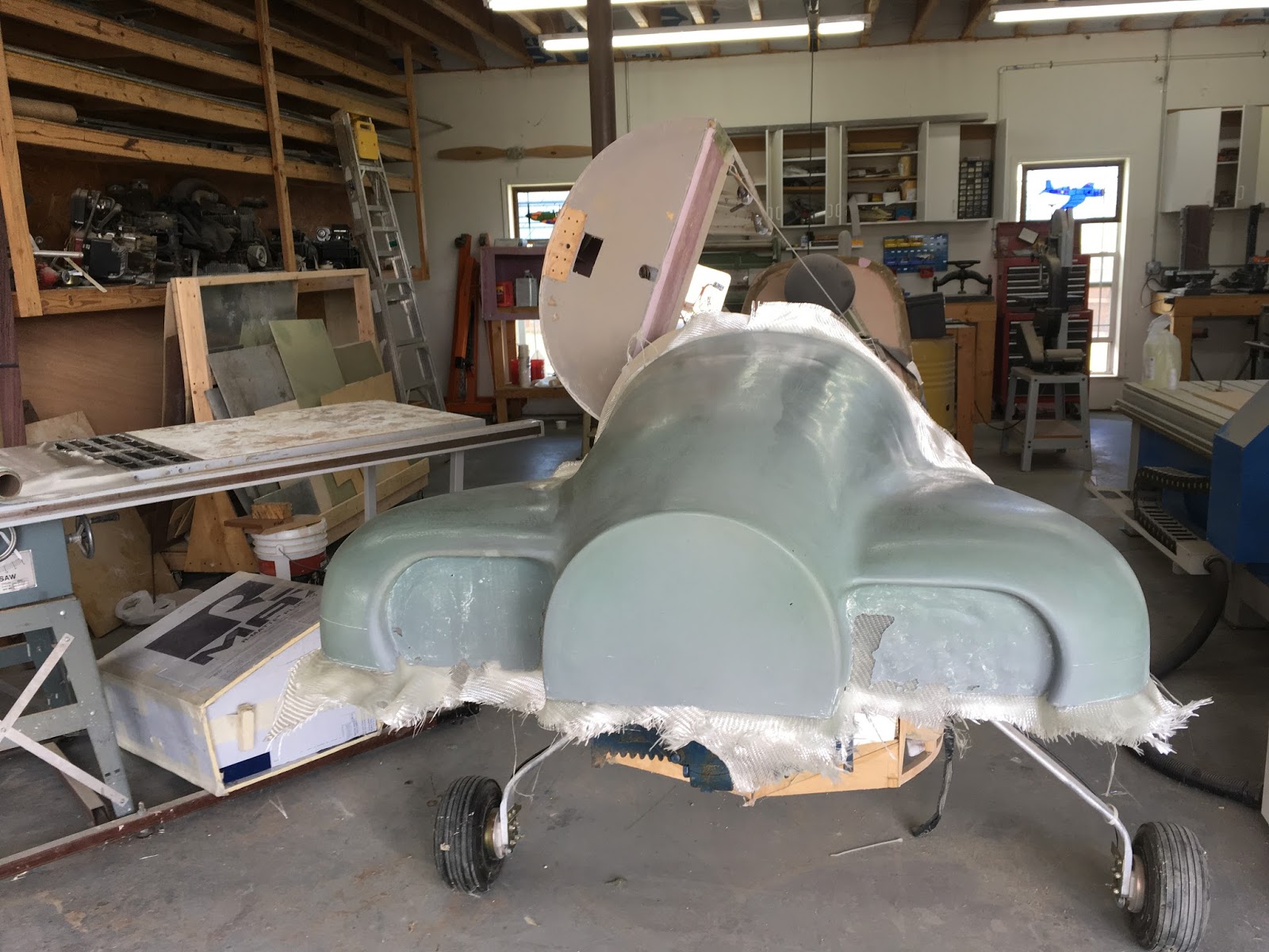
In this heat it took about 2 hours to fully cure. I got out my Milwaukee Sawzall and trimmed the flange back. I have about 2" of overlap left. I then drilled a series of 1/4"holes to lock both parts together. I decided that the plaster was going to get trashed after this, so I didn't care if I damaged it removing the tools. One tool is sufficient to lay up the lower cowl, but the second tool will have to be added to the first lay up the upper cowl.
 . . |
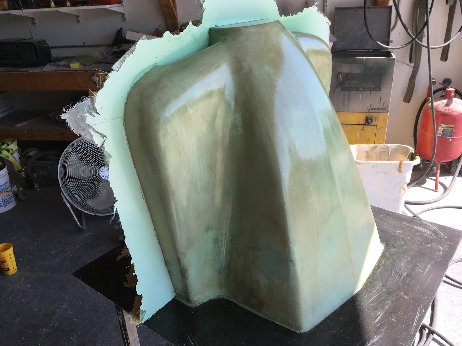
| Finished tool |
The tool is released and then cleaned with water to remove traces of the PVA. The surface is wet sanded with 320 grit paper until perfectly smooth. The constant reversal of surfaces in this process means that the final surface finish gets better and better. Lows become highs and highs become lows. sanding ridges are easily removed at this stage. The only line I want to keep is the trim line that is now a resin ridge. I will carefully rescribe that line back into the mold. Next step is the cowl lay up!!