Welcome to my Robin Blog.

It was suggested to me that I start a Blog on my ultralight project the "Robin". I have been working on this project for 4 years. On one of my first days at Vought aircraft, a stress man and future friend named Kenny Andersen walked up to me and said, "Aren't you the Mark Calder that designed the Wren Ultralight" Why yes I am I said. "well what have you done lately?" That was the genesis of the Robin design. The first 2.5 have been spent in the design phase. Actual construction started 1.5 years ago and has actually progressed smoothly. There have been a number of changes from the onset, but for the most part it is following my original concept. I will eventually sell plans for the Robin and make available all molded parts, fittings and welded assemblies. The Robin is designed to FAA part 103 and as such requires no pilots license to fly, although I think its a good idea to actually learn how to fly!! The actual name "Robin" was my Daughter Jamie's idea, I asked her to name the design based on my "cute little bird" theme (Wren)


Every good aircraft design has a "Mission" in mind before the actual design is started. A good designer will refer back to this mission every time a design decision must be made. Good design after all is just a series of good design decisions. On my first Ultralight design the Wren, the mission was to design a high performance low powered aircraft. The reduction of drag was the prime concern. I had been flying powered Hang gliders prior to this and because of this experience, I placed a high priority on climb performance. While most designers chose bigger engines, I chose lower drag and high aspect ratio (low span loading) wings. The Wren could out climb conventional Ultralight with up to 65 hp. The Robin follows this philosophy, but tries to improve on the performance of the Wren. Ultralight are not built by "rich" people, they offer an inexpensive means to enjoy one of the greatest experiences of my life, low speed soaring and flying.


Design Concept


The cost of an aircraft is directly proportional to its weight. , if low drag can be achieved then lighter and cheaper engines can be used. The Robin expands on the design mission of the Wren by using a longer span (40') wing and using a low speed laminar flow airfoil, (Wortmann FX 170) The leading edge of the wing on the prototype is molded fiber glass. The spar has been placed at 33% of the wing chord because the chosen airfoil is laminar over the first 32%. The aft covering is light weight Dacron Fabric. The leading edge of this fabric is purposely pinked and placed at the 32% chord point to facilitate laminar transition and elimination of separation bubbles. The main difference between the original design of the Robin and the current final design is the elimination of the single mono wheel retractable landing gear. Part 103 does not allow for a retractable landing gear. Which is really unfortunate because I spent a long time designing a really neat mechanism!!

In the course of the 4 years I have worked on the Robin, the structural design concept has evolved radically. Originally I was going to draw on the design of the Wren and use essential the same construction concepts. The original design of the Wren was heavily influenced by my Friend Steve Wood's Sky Pup design. I lived in Wichita Kansas and worked at Cessna Aircraft along with Steve. I watched his progress on the Pup and was very impressed with his concepts. I adapted the concept of using Styrofoam sheeting as the shear panels for the fuselage and the wing ribs. I did not however use the foam for the shear webs of the wing as Steve did. I originally wanted to build the fuselage of the Robin in a similar manner. Weight and the desire to not use foam for the basic structure due to the danger of fuel leaking eventually drove me to a all wood fuselage design. The wings were designed to take advantage of the Graphlite carbon pultruded material pioneered for the experimental aircraft by Jim Marske. I was familiar with this product from my experience at Bell Helicopter where it was considered in the construction of the V-22 wing.


Fiberglass cowl mock up

I just completed the lay up and fitting of the fiberglass mock up cowls, spinner and spinner backing plate. I decided to make some scrap fiberglass parts first so I could set the final trim lines and locate the attach fasteners. I used fiberglass because i could see thru it and measure from the edge of the mating structure underneath the cowl. The final parts will be 2 ply's of 7 oz Graphite cloth. I don't want to scrap those parts!! the material is $32/yd compared to $4.90/yd for glass.

scrap parts
As you can see from this picture.The cowling is translucent and the sub structure was visible. All in all the cowling fit very well. Even so, I will still not drill mating holes in the lower graphite cowl. I will match drill those holes from the upper cowl. The cowl will be fastened with countersunk screws into a nut plate riveted to the lower cowl.


view looking aft
this is a good view of the asymmetrical cowling. i chose to do this because I will flow the air over the single cylinder. The inlet will have some foam blocks added to the inlet lip that will act as a flow diffuser.  The idea is to slow the air down before it turns the corner. Heat added when it flows across the head will recover the pressure loss. its very critical that this cowl be fully sealed. a series of aluminum and silicon baffle plates need to be fabricates. as does an aluminum heat shield for the exhaust. The next step will be to cut out the out let around the tuned pipe.


another view without the spinner

The cowl will be pretty light. The final parts should weigh in at just over a pound.


graphite backing plate

This is the graphite spinner backing plate. although I only used 3 ply's of 7 oz graphite, it is half the weight of the 7 ply fiberglass mock up, yet it is at least 10 times stiffer. I will wet sand the resin line that is visible. this is the joint between the two mold half's. I will chuck this part in my lathe in the 3 jaw chuck to register the center, This will be a check to see if I located the center true enough in the mold.


On another unrelated note, I am now back in Design at my company Triumph/Vought. I am working on a manned/unmanned program based on the Berkut Home built. We are designing a larger version. I had the pleasure last week of meeting Dave Ronnenberg, the designer and builder of the Berkut. I was invited late this week to come out to Santa Monica and fly the Berkut by Dave. I'm sure we will also talk about some structural issues!!!I leave tomorrow morning for Santa Monica via San Diego. My friend Mike and Neal La France are going to pick me up at the Santa Monica airport in a Luscombe Sedan  and fly us back to Gillespie field in San Diego. Neal and Mike are old friends from my early Wichita days. its been years since I have seen them.

Lower Engine cowl, spinner backing plate molds and parts.

Well my traveling is finally over and I am now able to make real progress on my Robin. I have completed the upper cowl mold and at this time I have laid up and pulled a fiberglass mock up part. I need to fit the cowls together and locate the attaching fastener locations and layout the final trims so i can transfer this information back to the cowl molds in the form of scribe lines. I am using one ply of 8oz graphite fabric for each of the upper and lower cowls. There will be a thicker build up at the edge band for greater bearing on the attach fasteners and to match the .080 offset gap at the overlap. At the same time I laid up the mock up cowl, I also made a mold for the spinner backing plate. Again this first part was fiberglass and for the same reasons.
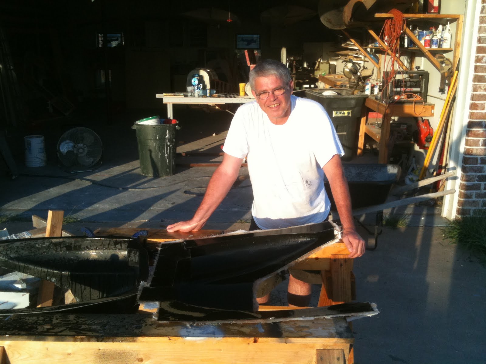
The happy builder
The photo to the left has been doctored for the more sensitive blog readers (I have a T shirt on) normally I work out in my shop in just shorts and shoes. Its been over 100 degrees here every day for 2 weeks. in this picture I was wet sanding the molds with 1200 grit wet paper. This removes the small lines, waves and imperfections that are left from the parting agent. The smoother the mold the easier the parts will release.


Both molds were wet sanded and trimmed. The molds need to be "seasoned" before they are ready for lay up. This means coat after coat of Carnuba based mold release wax. In between every coat the surface is water hardened (spit shined). The reason for this is to create multiple shear planes for the release wax. I will   coat each mold at least 9 times before I lay up in them, because wax and elbow grease is  hell of a lot cheaper than making a new mold.
upper and lower cowl molds


Its always a good idea to plan for excess on the mold surface and to incorporate a 90 degree flange like the ones shown. this allows the mold to keep its dimensional stability. I will make a foam supporting frame that will be fiberglassed to the mold shell. This aids in the actual lay up and also adds to mold stability.


There needs to be a spinner backing plate that sits between the prop flange and the prop. Since I want to use countersunk fasteners and nut plates to attach the spinner, I need to build the spinner with about 1/8" edge flange thickness. This means that the backing plate must sit 1/8" inside the inside mold line (inside surface0 of the spinner. I decided to modify the original spinner master model because I could then ensure that the spinner plate would run true and concentric. Nothing is more embarrassing that a wobbling spinner!! So I set the mold back into my lathe. I dialed it in concentric so I has less than .004" run out. I then cut a .125" parallel offset. 
backing plate mold construction

The backing plate mold started by making a centering plug out of Teflon. You can just make out the small white triangle in the center of the mold. A masonite divider plate was fabricated to span the mold. A small v groove was filed so that the centering nib would be exactly at the center line of the parting plane. Gel coat was sprayed on and non directional roving mat was used with polyester tooling resin for the lay up. After the resin cured I removed the divider and then drilled 4 partial holes into the 1st half of the mold. These will act as centering and alignment pins for the opposite half.

Backing plate mold
Here is the final Backing plate mold. I will keep the mold bolted together so the gap never warps or creeps. I made a circular cutting pattern for the fiberglass. I also made a smaller circular pattern out of Masonite that I used as a lay up aid. I set the masonite onto the round cloth and then folded the excess on top of it. I held it in place with another Masonite plate. the idea here is to keep the flange material folded away until I could unfold them and into the mold. This worked quite well. The final graphite backing plate will only be 3 ply's.


Spinner, prop hub and upper cowl

All of these parts are for trial fit up, as you can see the fiberglass is opaque and this allows me to locate the fasteners with correct edge margin from the underlying structure. The hub by the way is for a ground adjustable prop. I plan on using this to dial in the correct pitch needed. I will then fabricate a laminated spruce prop to save the weight.


View thru the inlet
So the cooling method I will use will be to bring the air into a diffuser inlet to slow it down. I will divert a small portion to a sealed filter box for the carb. The rest of the air will slow down and turn 90 degrees to the left. a series of baffles will ensure that this air only passes across the cylinder head and fins. The outlet will be on the opposite side of the cowl thru a hole cut in the r/h cheek cowl. In this exit area I will place 90% of the tuned pipe.
By the way, this blog allows comments from the readers, i would be interested in any feed back.