Squawk list burn down
I had a week off from work due to the 4th of July holiday, a few vacation days and a summons to appear for a Grand Jury!! I didn't get picked for the Grand Jury, but it sure wasted 1/2 a working day!! All of This means I got to work on my Robin for long uninterrupted periods. My original plan was to assemble the airplane at Midway Airport near Midlothian Texas, but cooling problems, traced to a bad head design, and carburetor leakage side tracked me from all of the small final jobs. The MZ 34 cooling issue was first on my plate, I discovered a few weeks ago that the head was retaining too much heat and when I tried to shut her down, she continued to run in diesel mode. This turned out to be a poorly designed head, why I had to pay for a new head, is beyond me and making me consider my choice of engine, but non the less, I received a new redesigned head from Compact radial engines and when I installed it, It seems to have solved the heating problem. |
| MZ 34 with new head |
Another nagging issue with the design, was the final design of the seat. All along I knew I needed to build a head rest, but I didn't think it would be a big deal. My friend Ed came over and we shot a series of pictures with mocked up head supports. It became apparent that by just supporting the head, the pilot would be choked, because his upper shoulders were not supported. I decided to modify the seat to add the upper support. This was quite easy because of the way the seat was made. sanded off a 4 inch wide section of the inner skin and exposed the foam core. I made two patterns out of Styrofoam and then clamped the seat the form blocks. I then lain up another ply of 8 oz fiberglass over the core.
 |
| bonding supports |
 |
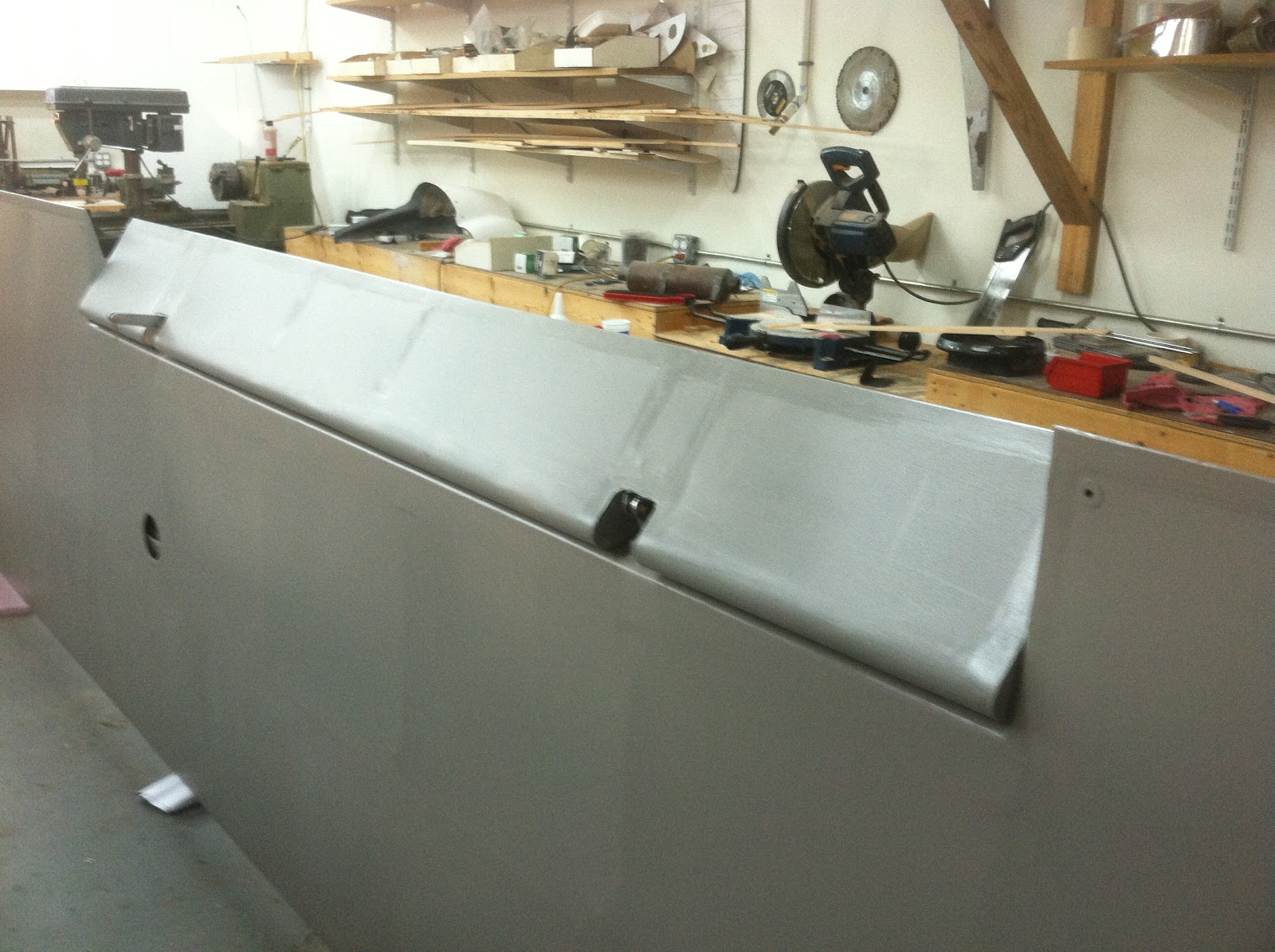
| upper seat support |
I need to rebuild the triangular rib and adjust the flat pattern slightly. But this shows the support clearly. I will build a light weigh aluminum head rest on top of this. That will support the head cushion. The white color by the way, is protective plastic that will come off eventually.
Another project was to do the final rig of the ailerons and cut a cable exit slit in the wing.
 |
| Right wing and aileron |
This is a picture of the right wing, the left wing was already finished.
Where the wing interfaces with the fuselage, there are slits that needed to be cut in the fuselage skin for the leading edge attach fitting and the aileron cables. I located the areas, added fabric doublers and then added felt seals.
 |
| Felt exit seals |
I will touch up the paint after I am done adding the seals.
 |
| Leading edge felt seal |
Before a doubler is added, the old paint is removed with a solvent wipe with MEK. It works quite well!!
I am continuing work on the seat support and head rest. Nest week I should have the final engine run with the cowl and baffle, hopefully this is all I will need to do before the first taxi test.
