Welcome to my Robin Blog.

It was suggested to me that I start a Blog on my ultralight project the "Robin". I have been working on this project for 4 years. On one of my first days at Vought aircraft, a stress man and future friend named Kenny Andersen walked up to me and said, "Aren't you the Mark Calder that designed the Wren Ultralight" Why yes I am I said. "well what have you done lately?" That was the genesis of the Robin design. The first 2.5 have been spent in the design phase. Actual construction started 1.5 years ago and has actually progressed smoothly. There have been a number of changes from the onset, but for the most part it is following my original concept. I will eventually sell plans for the Robin and make available all molded parts, fittings and welded assemblies. The Robin is designed to FAA part 103 and as such requires no pilots license to fly, although I think its a good idea to actually learn how to fly!! The actual name "Robin" was my Daughter Jamie's idea, I asked her to name the design based on my "cute little bird" theme (Wren)


Every good aircraft design has a "Mission" in mind before the actual design is started. A good designer will refer back to this mission every time a design decision must be made. Good design after all is just a series of good design decisions. On my first Ultralight design the Wren, the mission was to design a high performance low powered aircraft. The reduction of drag was the prime concern. I had been flying powered Hang gliders prior to this and because of this experience, I placed a high priority on climb performance. While most designers chose bigger engines, I chose lower drag and high aspect ratio (low span loading) wings. The Wren could out climb conventional Ultralight with up to 65 hp. The Robin follows this philosophy, but tries to improve on the performance of the Wren. Ultralight are not built by "rich" people, they offer an inexpensive means to enjoy one of the greatest experiences of my life, low speed soaring and flying.


Design Concept


The cost of an aircraft is directly proportional to its weight. , if low drag can be achieved then lighter and cheaper engines can be used. The Robin expands on the design mission of the Wren by using a longer span (40') wing and using a low speed laminar flow airfoil, (Wortmann FX 170) The leading edge of the wing on the prototype is molded fiber glass. The spar has been placed at 33% of the wing chord because the chosen airfoil is laminar over the first 32%. The aft covering is light weight Dacron Fabric. The leading edge of this fabric is purposely pinked and placed at the 32% chord point to facilitate laminar transition and elimination of separation bubbles. The main difference between the original design of the Robin and the current final design is the elimination of the single mono wheel retractable landing gear. Part 103 does not allow for a retractable landing gear. Which is really unfortunate because I spent a long time designing a really neat mechanism!!

In the course of the 4 years I have worked on the Robin, the structural design concept has evolved radically. Originally I was going to draw on the design of the Wren and use essential the same construction concepts. The original design of the Wren was heavily influenced by my Friend Steve Wood's Sky Pup design. I lived in Wichita Kansas and worked at Cessna Aircraft along with Steve. I watched his progress on the Pup and was very impressed with his concepts. I adapted the concept of using Styrofoam sheeting as the shear panels for the fuselage and the wing ribs. I did not however use the foam for the shear webs of the wing as Steve did. I originally wanted to build the fuselage of the Robin in a similar manner. Weight and the desire to not use foam for the basic structure due to the danger of fuel leaking eventually drove me to a all wood fuselage design. The wings were designed to take advantage of the Graphlite carbon pultruded material pioneered for the experimental aircraft by Jim Marske. I was familiar with this product from my experience at Bell Helicopter where it was considered in the construction of the V-22 wing.


First part

I finished laying up the upper cowl. I have a neat trick that works very well that I will share. The process of contact wet lay up, that is so familiar with the home built airplane crowd, is by its nature, very porous. If you were to lay up directly on a mold, and then shoot a coat of primer, the surface would be covered with thousands of pin holes. These are the result of the paint being wicked into the laminate due to capillary action. your next task would be to spend hours filling and fairing with either more primer or with spot putty. Very time consuming. So the way you avoid this is to shoot the mold with your primer BEFORE you do the lay up. Here are some pictures of the lay up steps.


Adding trim scribe
In this picture I am scribing the trim line. The trim line has reversed during the molding process from a low to a high. I need to scribe it into the mold surface before I wet sand the mold to finish the final surface. If I didn't scribe it, I would lose it in that step. The mold was wet sanded with 200 grit paper to remove all surface imperfections. The mold was then seasoned with 7 coats of carnauba paste wax.


PVA being shot
In this picture I am again shooting Partall 10 PVA. (Poly Vinyl Acetate)  This is a water soluble release film. I have never lost a part when I use Partall 10. I really swear by this stuff. To properly apply it you must build up thickness gradually. In the case of this mold and in this weather (90 degrees F) it took 6 light coats. The PVA is allowed to fully dry between coats. In this weather it only took about 5 minutes per coat. Do not get anxious and try to shoot a single thick coat. You will get runs and the coat will be ruined. The next step after the PVA cures is to shoot the high solids primer. Because the PVA is water soluble. it needs to be applied just prior to lay up. if you let is set overnight in any kind of humidity, it will start to bubble up. I shot the primer until the surface was fully coated. I shot 4 light coats, again building the thickness slowly. Once the primer had dried (about 20 minutes) I laid up 3 ply's of Rutan 285 BID cloth.  It took 20 hours to cure sufficiently to the point where I could release it.

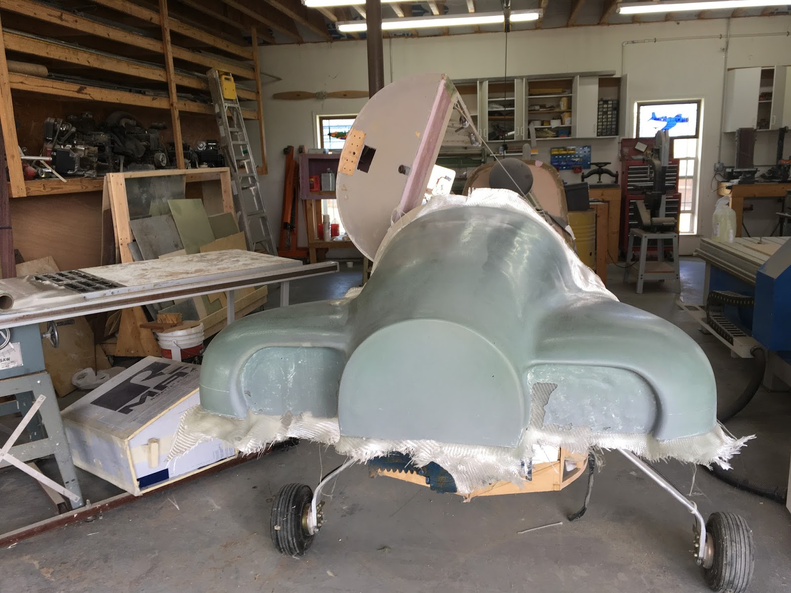
Upper cowl untrimmed
Here is the final result. The part released with a full film of PVA. I few minutes under the hose and the surface was totally clean. This is why I have never had a part stick with PVA film. If a part appeared to be "Stuck" all you have to do is peel back an edge and pour some water into the opening. eventually the water will wick completely through the PVA. at that point nothing is holding it on. The next step is to lay up the lower half. That will be a little more difficult because I need to attach the upper cowl mold to the lower cowl mold. The lower cowl trims to the same line as the upper. I also need to lay up an overlap flange. I have a good idea for this and I will cover that and a slick method of trimming fiberglass that completely eliminates the possibility of edge damage and delamination. I will cover that next

No comments: