When I left off on the cowl, I had flipped the Robin over and supported her with a false spar attached to the wing spar attach bulkhead. The fiber glass surface of the cowl was sanded down to knockoff the high spots. A coat of automotive bondo was then swept over the entire surface. The first goal of the final sanding is to eliminate large waves in the surface. Later the goal will be to fill small pin holes and divots.
 |
| initial rough sanding |
I will sweep in the junction between the cheek cowl and the cowl side. In order to do this I want both surfaces to be relatively wave free. I added additional bondo on both of these surfaces and used my air file board to level them.
 |
| new circular drag |
I made a larger Circular drag for the lower surfaces. The method I use is to sweep the fillet in 3 stages.
 |
| 1st sweep |
After the first sweep, I let the bondo cure and knock off high spots with a tubular sander with 36 grit paper stuck to it. There is no sense in using anything finer at the initial stages.
 |
| 2nd sweep |
Again, I let every thing cure and then knocked down the high points with a tubular sanding block. I used flat sanders on the flat areas and tubular sanders for inside fillets and compound contour areas. Never mix the two because you will leave streaks in the bondo.
 |
| third sweep |
As you can see the fillet is fully formed. I swept a thinned coat of Bondo over the entire surface. I thinned the Bondo with a product called resin honey. Its actually Styrene monomer. It thins out the Bondo and will fully cure once it is catalyzed. After the entire surface is swept with thinned Bondo, I drop down to 80 grit and continue leveling the surface. I am now paying attention to small depressions and pin holes.
 |
| blocked out with 80 grit |
I'm getting pretty close to a wave free surface. At this point its time to remove the spinner. The actual cowl needs to close up the area around the crankshaft. The spinner was added initially to aid in the fairing of the foam blocks.
 |
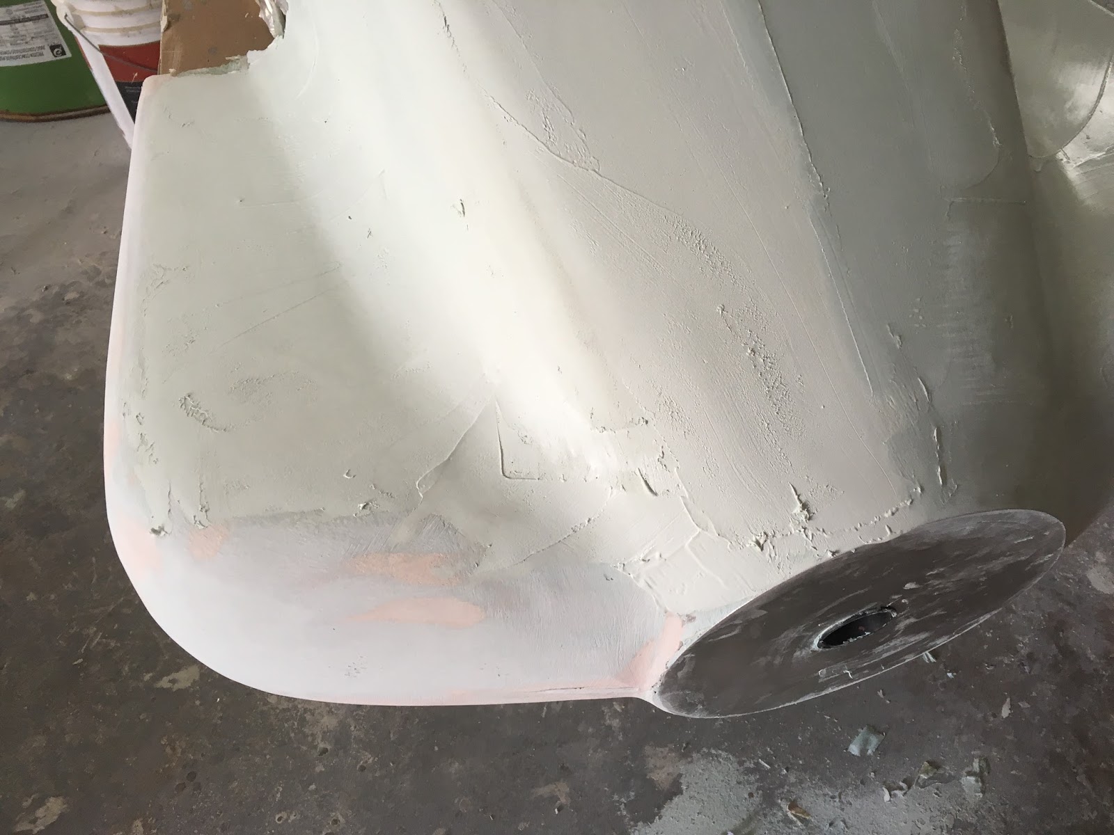
| spinner disc installed |
I cut a disk of aluminum the same diameter as the spinner base. I also cut a 2" hole in the center that matched the crankshaft prop hub flange. This centers the disk. I used Bondo to bond the disk to the exposed foam in the cowl. I then added Bondo around the edge of the disk to fill in gaps between the disk and the cowl surface.
 |
| finished disk |
More filling and sanding and the cowl is now ready for its last fill and sand step. I will use a catalyzed spot putty.
 |
| spot putty |
Spot putty is like bondo but much thinner and consists entirely of hollow micro balloon sphere filler. This makes it much easier to sand and allows me to now drop to 180 grit sanding paper.
 |
| spot putty coat |
The entire surface is coated and then blocked out using 180 grit paper.
 |
| sand able primer |
After sanding the spot putty, I sprayed a coat of high solids filling primer. This is super easy sand-able paint and is used to fill sanding marks. The paint is blocked out with 220 grit paper. After the sanding is finished I used a LED flash light to inspect the complete surface looking for minor imperfections and pin holes. I circled every defect with a sharpie and re coated locally with spot putty
 |
| inspected surface |
I also struck a level line in preparation for the next step I will add a split plane that will be used to form a flange on the fiber glass splash. I am not making the actual cowl mold here. Normally this step would he done with Ultra-cal Plaster, but that would add over 200 lbs to the fuselage which is already nose heavy. What I am making here is a lift of the OML (Outside Mold Line) surface of the cowl. I will still need to add inlets. That will come after I make the OML splashes.
 |
| split plane |
This is the beginning of the fabrication of the splash split plane. I was aided by 15 year old Eloi Mathieu. Eloi was a very enthusiastic helper. He is the Brother of Perrine Mathieu who once worked for me at Triumph Aerostructures. Eloi had his first opportunity to run a band saw. It took a few tries but he rapidly got the hang of it and cut out boards with very good precision. Its still not 100% possible to fill the small gaps between the board and cowl surface so the gap is filled in with modelling clay.
 |
| modelling clay |
This shows the precision of Eloi's cut vs mine. His board is on the left. The lower half of the cowl is now ready for 3 coats of PVA (Poly Vinyl Acetate) release agent. I need to be able to shoot gel coat within 12 hours of spraying PVA. In high humidity, the PVA will absorb water and swell.
Thats the subject of my next blog entry


No comments:
Post a Comment