My good friend Mike Lafrance and his wife Audrey flew out from San Diego for the week end. Mike and his Dad Neal are old friends from Wichita. I first met Neal at my first engineering job ever at Boeing Military Aircraft in Wichita Kansas. Neal was a designer on a very cool 'Black" program that eventually was made public and called "Pave Tiger" My involvement was packaging a tuned resonant exhaust chamber. Neal is one of the original founding members of the EAA, he was in the Wisconsin National Guard with Paul Poberezny when the idea for the Experimental Aviation Association was born. Neal has an award winning Wittman tailwind. he also built a Wittman V-Witt racer and actually raced against Steve Wittman in his final race. I owe Neal a great deal for all his support during the design and building of my old Wren and years later when I had a chance to repay his kindness I volunteered to design and build his cowl on his beautiful Culver STF (Steel Tube Fuselage).
 |
| Mike and Neal Flying the Cadet |
His son Mike is also quite an accomplished pilot, home builder and restorer. His Luscombe 8A and his 11A sedan are works of art!! it was sure good of Mike to burn his vacation helping me work on the Robin. The following pictures are a collage of our progress. We completed the rig of the rudder pedals, completed the reattachment of the fuel tank fairing and started adding the tip caps of the vert fin and rudder.
 |
| Mike assures me he is a better Pilot with a few beers in him LOL!! |
The Canopy in this picture is in the process of being finished for final paint.
I think Mike is drinking a Becks in this picture!!
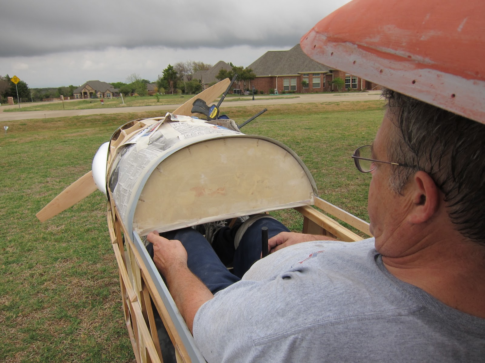
This actually was a test , Mike is 6'3" and the tallest person to sit in the cockpit. The rudder pedals easily adjusted to him, but we found that two tunnels need to be built into the instrument panel to allow for knee clearance. The final panel will have a 'T" layout.
 |
| Adding the rudder cable anchors. |
We learned a little lesson here, after the cables were rigged and the turnbuckles safety wired, I tried out the pedals and discovered they were canted too far aft. Mike came up with the solution of lengthening the Cable anchors. This had the effect of rotating the top of the pedal aft. The idea is that your heel needs to rest close to the pedal pivot.
 |
| FWD attach hinge |
The FWD Fairing was reattached using two Piano hinges. The hinges easily withdraw and once done, the fairing readily releases.
The White material on the firewall is the Ceramic fiberfrax paper
 |
| Rear attach hinge |
Later Mike added the plywood scallops. the purpose of these scallops is to smoothly transition the fabric from the stringers to the round bulkhead.
 |
| The happy builder!! |
I told Mike I never get tired of staring at the cowl and fuselage lines. He told me that the reason I will finish this project. I'm not loosing interest as I go!! Because I was travelling so much for the last 3 years, I never used my Vacation. I now "need" to take off the whole month of December or I will lose my vacation (Bummer!!)
I plan of doing all the cover and finish during that time. First flight will follow shortly afterward.
 |
| Me and Boo |
We decided to do a little photo shoot. Good ole Boo, he is always near me wherever I go. Always protecting me from those nasty Sheep, Cows and flying frisbees!!
 |
| Soaring eye view |
I learned a long time ago not to design for skinny people!! They usually don't have any Money!! LOL!! The width across the shoulders bottom and is 24" Compare this to the 18" in 1-26 sailplane. The need for the instrument tunnels is apparent in this picture
 |
| Foot position on the rudder pedals |
This is a very comfortable seat and rudder combination. The pedals are mid adjustment for me, they still have one more inch to go for Mike in the FWD position and can still adjust rearward another 9 inches. This pedal adjust works beautifully.
 |
| Rudder Foam block |
Work started on the Tip Caps for the Vertical Fin and Rudder. I am not making molds right away forr these parts. I am thinking I will need more Rudder. This is the technique a builder would use everywhere I have a compound molded part. The rudder was blocked in with some foam and then the edges were sanded parallel to the rudder surfaces.
 |
| Vert fin foam added |
I traced the curve of the rudder foam and then cut out the vert fin foam and then bonded it to the vert fin. The foam was then sanded parallel to the vert fin surface. I then locked the rudder in place and started profiling the foam in the side view with the sanding block
 |
| Final profile |
Scrap foam is used to sand the foam until the final finish is achieved. the rudder was separated and two layers of glass were added. a coat of micro balloon and epoxy was squeegeed onto the surface. This is very important, the foam is an open cell structure and if its not sealed, the resin laid on the glass will leech into the foam and cause a dry laminate.
I will follow up with the finished parts in the next entry


No comments:
Post a Comment