Welcome to my Robin Blog.

It was suggested to me that I start a Blog on my ultralight project the "Robin". I have been working on this project for 4 years. On one of my first days at Vought aircraft, a stress man and future friend named Kenny Andersen walked up to me and said, "Aren't you the Mark Calder that designed the Wren Ultralight" Why yes I am I said. "well what have you done lately?" That was the genesis of the Robin design. The first 2.5 have been spent in the design phase. Actual construction started 1.5 years ago and has actually progressed smoothly. There have been a number of changes from the onset, but for the most part it is following my original concept. I will eventually sell plans for the Robin and make available all molded parts, fittings and welded assemblies. The Robin is designed to FAA part 103 and as such requires no pilots license to fly, although I think its a good idea to actually learn how to fly!! The actual name "Robin" was my Daughter Jamie's idea, I asked her to name the design based on my "cute little bird" theme (Wren)


Every good aircraft design has a "Mission" in mind before the actual design is started. A good designer will refer back to this mission every time a design decision must be made. Good design after all is just a series of good design decisions. On my first Ultralight design the Wren, the mission was to design a high performance low powered aircraft. The reduction of drag was the prime concern. I had been flying powered Hang gliders prior to this and because of this experience, I placed a high priority on climb performance. While most designers chose bigger engines, I chose lower drag and high aspect ratio (low span loading) wings. The Wren could out climb conventional Ultralight with up to 65 hp. The Robin follows this philosophy, but tries to improve on the performance of the Wren. Ultralight are not built by "rich" people, they offer an inexpensive means to enjoy one of the greatest experiences of my life, low speed soaring and flying.


Design Concept


The cost of an aircraft is directly proportional to its weight. , if low drag can be achieved then lighter and cheaper engines can be used. The Robin expands on the design mission of the Wren by using a longer span (40') wing and using a low speed laminar flow airfoil, (Wortmann FX 170) The leading edge of the wing on the prototype is molded fiber glass. The spar has been placed at 33% of the wing chord because the chosen airfoil is laminar over the first 32%. The aft covering is light weight Dacron Fabric. The leading edge of this fabric is purposely pinked and placed at the 32% chord point to facilitate laminar transition and elimination of separation bubbles. The main difference between the original design of the Robin and the current final design is the elimination of the single mono wheel retractable landing gear. Part 103 does not allow for a retractable landing gear. Which is really unfortunate because I spent a long time designing a really neat mechanism!!

In the course of the 4 years I have worked on the Robin, the structural design concept has evolved radically. Originally I was going to draw on the design of the Wren and use essential the same construction concepts. The original design of the Wren was heavily influenced by my Friend Steve Wood's Sky Pup design. I lived in Wichita Kansas and worked at Cessna Aircraft along with Steve. I watched his progress on the Pup and was very impressed with his concepts. I adapted the concept of using Styrofoam sheeting as the shear panels for the fuselage and the wing ribs. I did not however use the foam for the shear webs of the wing as Steve did. I originally wanted to build the fuselage of the Robin in a similar manner. Weight and the desire to not use foam for the basic structure due to the danger of fuel leaking eventually drove me to a all wood fuselage design. The wings were designed to take advantage of the Graphlite carbon pultruded material pioneered for the experimental aircraft by Jim Marske. I was familiar with this product from my experience at Bell Helicopter where it was considered in the construction of the V-22 wing.


FWD fairing and canopy attach

 The FWD fairing covers the fuel tank and provides the attach point for the Canopy hinge. The final fairing will be fabric covered and will be completed when the rest of the plane is covered.

View of the FWD fairing and fuel tank

 The fairing is made up of foam and glass sandwich panels of one ply of 120 style glass and 1/4" PVC foam core. $.5 lb/cu ft density was used. As an alternate, Last-A-Foam urethane foam can also be used. However its been my experience that Last-A-Foam rarely lasts thru shipping. its always coming in cracked. in preparation for the build, a sheet of foam was glassed and allowed to cure.


Templates used to cut foam board
 Templates are made from poster board. The layout is taken directly from the drawings. Again, do not lay out a full template, only lay out half and then copy it and past it together, or flip it over when cutting. this saves time and ensures a symmetrical curve.


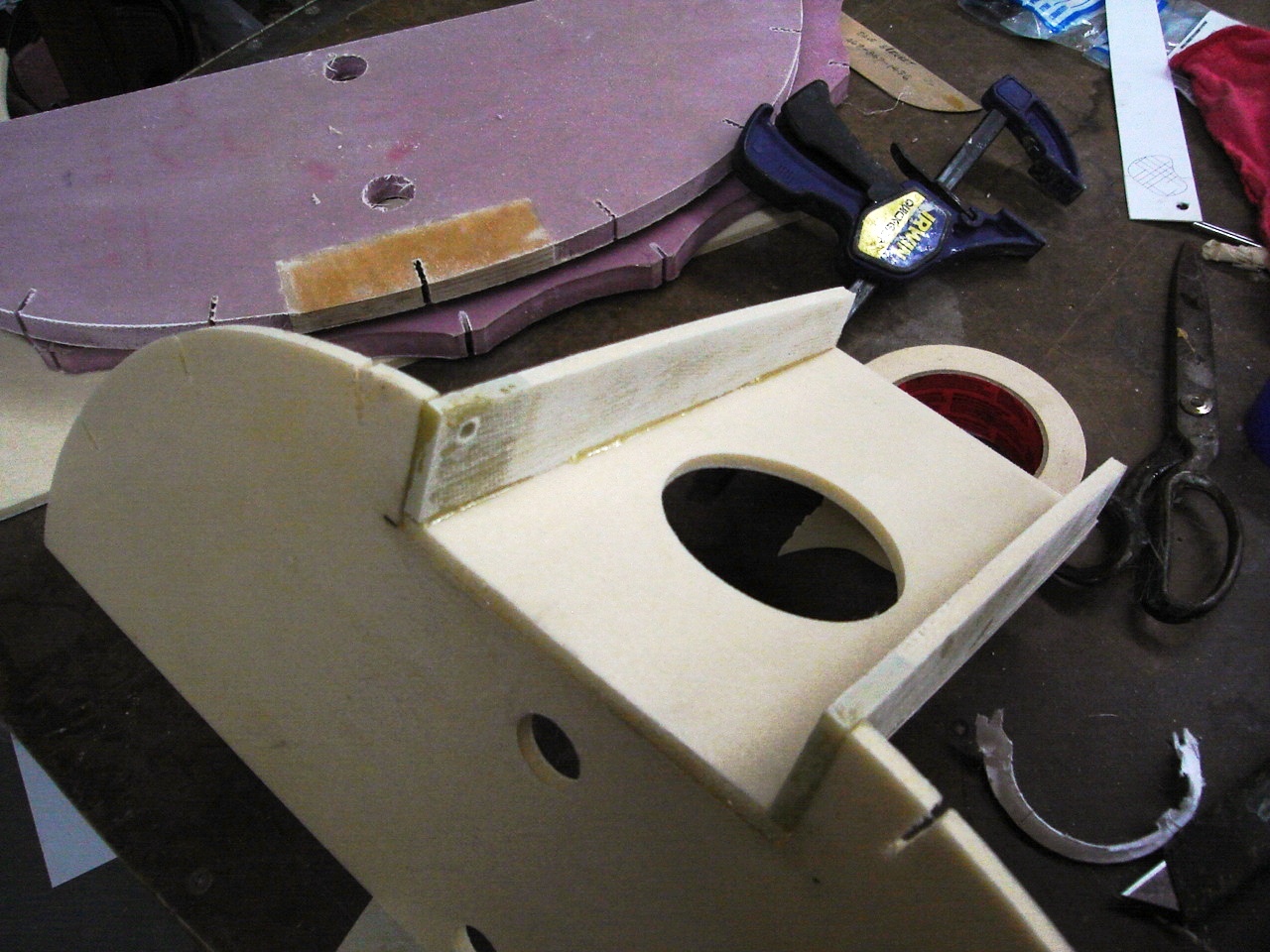
Canopy hinge beams and horizontal shear web
 The canopy hinge beams and the horizontal shear web are all assembled using 5 minute epoxy. The circular cut out is for the Fuel tank filler neck. Eventually the gap between the fuel tank and the shear web will be sealed. A small drain tube will allow spilt fuel to drain to the ground. After the panels are jigged with 5 minute Epoxy, they are fillet bonded with a fillet of flox. A 1/2" radius spreader is used.


adding stringers.

The Stringers function as fabric stand offs, only the center stringer is a straight line segment. Because of this and the need for the stringers to form to the curvature, the back side is notched. This effectively reduces the thickness of these stringers by the depth of the notch, so they are not adequate to resist the fabric tension. Later an inner "T" cap of 1/4" wide stock will be bonded to the notched edge to restore the stiffness. Excessive stringers are trimmed flush after they cure.


Finished FWD fairing


As in the aft Turtle Deck, fabric fairing strips are made from .032" plywood. They are made in "Situ" by first building a poster board template. The outline is traced on to the plywood.


Another View looking FWD

The blue fuel lines are for the sight gage mounted on the instrument panel.

No comments: