Welcome to my Robin Blog.

It was suggested to me that I start a Blog on my ultralight project the "Robin". I have been working on this project for 4 years. On one of my first days at Vought aircraft, a stress man and future friend named Kenny Andersen walked up to me and said, "Aren't you the Mark Calder that designed the Wren Ultralight" Why yes I am I said. "well what have you done lately?" That was the genesis of the Robin design. The first 2.5 have been spent in the design phase. Actual construction started 1.5 years ago and has actually progressed smoothly. There have been a number of changes from the onset, but for the most part it is following my original concept. I will eventually sell plans for the Robin and make available all molded parts, fittings and welded assemblies. The Robin is designed to FAA part 103 and as such requires no pilots license to fly, although I think its a good idea to actually learn how to fly!! The actual name "Robin" was my Daughter Jamie's idea, I asked her to name the design based on my "cute little bird" theme (Wren)


Every good aircraft design has a "Mission" in mind before the actual design is started. A good designer will refer back to this mission every time a design decision must be made. Good design after all is just a series of good design decisions. On my first Ultralight design the Wren, the mission was to design a high performance low powered aircraft. The reduction of drag was the prime concern. I had been flying powered Hang gliders prior to this and because of this experience, I placed a high priority on climb performance. While most designers chose bigger engines, I chose lower drag and high aspect ratio (low span loading) wings. The Wren could out climb conventional Ultralight with up to 65 hp. The Robin follows this philosophy, but tries to improve on the performance of the Wren. Ultralight are not built by "rich" people, they offer an inexpensive means to enjoy one of the greatest experiences of my life, low speed soaring and flying.


Design Concept


The cost of an aircraft is directly proportional to its weight. , if low drag can be achieved then lighter and cheaper engines can be used. The Robin expands on the design mission of the Wren by using a longer span (40') wing and using a low speed laminar flow airfoil, (Wortmann FX 170) The leading edge of the wing on the prototype is molded fiber glass. The spar has been placed at 33% of the wing chord because the chosen airfoil is laminar over the first 32%. The aft covering is light weight Dacron Fabric. The leading edge of this fabric is purposely pinked and placed at the 32% chord point to facilitate laminar transition and elimination of separation bubbles. The main difference between the original design of the Robin and the current final design is the elimination of the single mono wheel retractable landing gear. Part 103 does not allow for a retractable landing gear. Which is really unfortunate because I spent a long time designing a really neat mechanism!!

In the course of the 4 years I have worked on the Robin, the structural design concept has evolved radically. Originally I was going to draw on the design of the Wren and use essential the same construction concepts. The original design of the Wren was heavily influenced by my Friend Steve Wood's Sky Pup design. I lived in Wichita Kansas and worked at Cessna Aircraft along with Steve. I watched his progress on the Pup and was very impressed with his concepts. I adapted the concept of using Styrofoam sheeting as the shear panels for the fuselage and the wing ribs. I did not however use the foam for the shear webs of the wing as Steve did. I originally wanted to build the fuselage of the Robin in a similar manner. Weight and the desire to not use foam for the basic structure due to the danger of fuel leaking eventually drove me to a all wood fuselage design. The wings were designed to take advantage of the Graphlite carbon pultruded material pioneered for the experimental aircraft by Jim Marske. I was familiar with this product from my experience at Bell Helicopter where it was considered in the construction of the V-22 wing.


Progress, Squawk list burn down!!

My good friend Mike Lafrance and his wife Audrey flew out from San Diego for the week end. Mike and his Dad Neal are old friends from Wichita. I first met Neal at my first engineering job ever at Boeing Military Aircraft in Wichita Kansas. Neal was a designer on a very cool 'Black" program that eventually was made public and called "Pave Tiger" My involvement was packaging a tuned resonant exhaust chamber. Neal is one of the original founding members of the EAA, he was in the Wisconsin National Guard with Paul Poberezny when the idea for the Experimental Aviation Association was born. Neal has an award winning Wittman tailwind. he also built a Wittman V-Witt racer and actually raced against Steve Wittman in his final race. I owe Neal a great deal for all his support during the design and building of my old Wren and  years later when I had a chance to repay his kindness I volunteered to design and build his cowl on his beautiful Culver STF (Steel Tube Fuselage).
Mike and Neal Flying the Cadet

 His son Mike is also quite an accomplished pilot, home builder and restorer. His Luscombe 8A and his 11A sedan are works of art!! it was sure good of Mike to burn his vacation helping me work on the Robin. The following pictures are a collage of our progress. We completed the rig of the rudder pedals, completed the reattachment of the fuel tank fairing and started adding the tip caps of the vert fin and rudder.
Mike assures me he is a better Pilot with a few beers in him LOL!!
The Canopy in this picture is in the process of being finished for final paint.
I think Mike is drinking a Becks in this picture!!
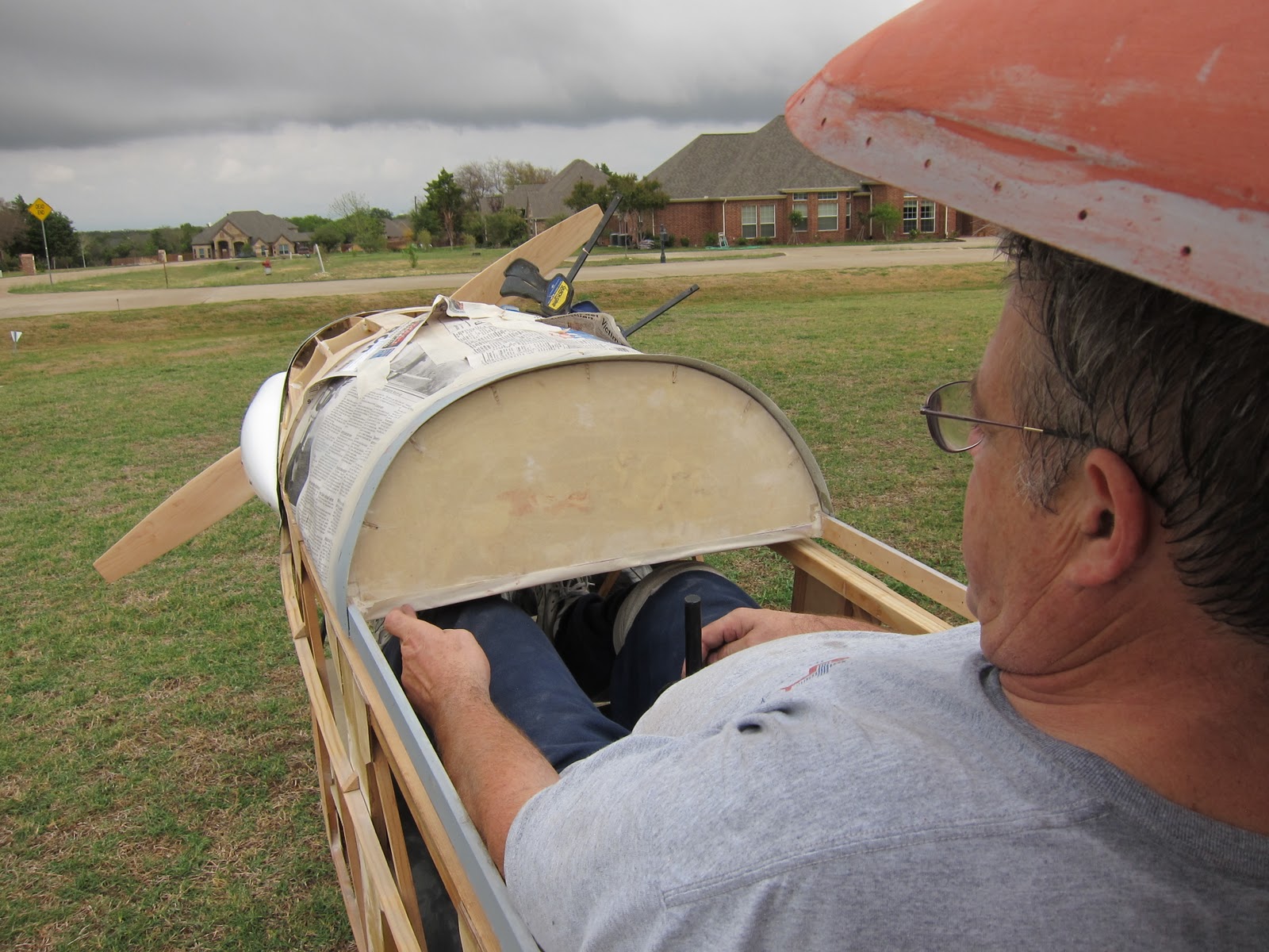
This actually was a test , Mike is 6'3" and the tallest person to sit in the cockpit. The rudder pedals easily adjusted to him, but we found that two tunnels need to be built into the instrument panel to allow for knee clearance. The final panel will have a 'T" layout.
Adding the rudder cable anchors.
We learned a little lesson here, after the cables were rigged and the turnbuckles safety wired, I tried out the pedals and discovered they were canted too far aft. Mike came up with the solution of lengthening the Cable anchors. This had the effect of rotating the top of the pedal aft. The idea is that your heel needs to rest close to the pedal pivot.


FWD attach hinge
The FWD Fairing was reattached using two Piano hinges. The hinges easily withdraw and once done, the fairing readily releases.
The White material on the firewall is the Ceramic fiberfrax paper


Rear attach hinge
Later Mike added the plywood scallops. the purpose of these scallops is to smoothly transition the fabric from the stringers to the round bulkhead.


The happy builder!!
I told Mike I never get tired of staring at the cowl and fuselage lines. He told me that the reason I will finish this project. I'm not loosing interest as I go!!  Because I was travelling so much for the last 3 years, I never used my Vacation. I now "need" to take off the whole month of December or I will lose my vacation (Bummer!!)
I plan of doing all the cover and finish during that time. First flight will follow shortly afterward.


Me and Boo
We decided to do a little photo shoot. Good ole Boo, he is always near me wherever I go. Always protecting me from those nasty Sheep, Cows and flying frisbees!!


Soaring eye view
I learned a long time ago not to design for skinny people!!  They usually don't have any Money!! LOL!! The width across the shoulders bottom and is 24" Compare this to the 18" in 1-26 sailplane. The need for the instrument tunnels is apparent in this picture


Foot position on the rudder pedals
This is a very comfortable seat and rudder combination.  The pedals are mid adjustment for me, they still have one more inch to go for Mike in the FWD position and can still adjust rearward another 9 inches. This pedal adjust works beautifully.

Rudder Foam block
Work started on the Tip Caps for the Vertical Fin and Rudder. I am not making molds right away forr these parts. I am thinking I will need more Rudder. This is the technique a builder would use everywhere I have a compound molded part. The rudder was blocked in with some foam and then the edges were sanded parallel to the rudder surfaces.
Vert fin foam added

I traced the curve of the rudder foam and then cut out the vert fin foam and then bonded it to the vert fin. The foam was then sanded parallel to the vert fin surface. I then locked the rudder in place and started profiling the foam in the side view with the sanding block


Final profile
Scrap foam is used to sand the foam until the final finish is achieved. the rudder was separated and two layers of glass were added. a coat of micro balloon and epoxy was squeegeed onto the surface. This is very important, the foam is an open cell structure and if its not sealed, the resin laid on the glass will leech into the foam and cause a dry laminate.

I will follow up with the finished parts in the next entry


Omissions, mistakes and other excuses!!!

There has been a nagging problem since the day I installed the fuel tank, no access after it was installed. I always figured I would correct this problem when I drew up the final set of plans, but I began to realize that if I have any fuel tank issues after I cover the plane, it will take a week to repair it.  So I decided to bite the bullet and just fix it. This is all the more necessary because I just bought a set of beautiful Belite Instruments from Jim Weibe in Wichita Ks. http://www.beliteaircraft.com/avionics/  One of the gauges he makes is an electronic fuel gauge. This requires the addition of a fuel probe. I would need access to the tank anyway. I have decided to make the front turtle deck that covers the fuel tank a separate piece. I will attach the Turtle deck with two hinges. Since the access is not required on a daily basis, this will work well. 

I began the process by removing the Front Turtle deck. I used a tool that has become indispensable in my shop. A Chicago Pneumatic Oscillating multi- tool. The product cleanly separated the turtle deck right through the existing bond. This tool is also very Handy when it comes to trimming cured fiberglass or Graphite. If you use a carbide tile grouting blade, it zips right through cured composites like nobodies business. 
Cut off Turtle deck

After I cut off the Turtle deck, I rechecked the weight. .4 lbs. I will have to rebuild this section by adding two horizontal longerons that will close out the section.
I also needed to "close out" the foam and glass panels at both edges to accepts the fasteners that will mount the hinge


Foam close out being added
 This is a typical Composite detail. When fasteners are introduced into composite, the core is usually increased locally in density to react the bolt clamp up loads, or the core is removed and the inner skin is transitioned to the outer skin or "closed out" I chose this method because this joint will be primarily in shear.


Fuselage sans the turtle deck

Unfortunately I had to remove the engine again. to do this modification.
its was a pain, but well worth the effort if I ever need to service the fuel tank.


Rudder Pedal "bow Sprit"

Another omission I righted this week end was the lack of a Pedal return spring on the rudder Pedals. I had to add a small extension tube "Bow Sprit" to attach the springs to.

I am getting pretty close, once these two jobs are finished, its on to installing the Instruments , throttle and wiring. After that is finished, I will re rig the wings and route the Aileron Cables. Then the last little job will be to make the tip caps of the Vert fin and the rudder. I am not going to make molds for these parts yet because my eyeball engineering and past ultralight experience tells me I may need more rudder. Everything is in proportion to the original RF4D, but the slower speed means the rudder and vert fin may not be as effective as the original. That's what flight tests are for.

Final Cowling pictures and internal Baffling


I have finished the fire wall forward. The Fiberfrax is installed, the latex primer is applied and the fuel and electrical wires have been run. The internal baffling is finished. I have some very thin countersunk Stainless steel washers that I am bonding to the surface at every fastener. This will reinforce the countersunk holes very cleanly.
L/H side


My Friend Ed ttp://mmwauto.com/index.php/services.html  did the final paint on these parts. As you can see from the pictures the finish is excellent. He has a huge down draft paint booth. Its big enough to fit both of my wings and the fuselage. The paint by the way was Summit racing single stage Ureathane paint. http://www.summitracing.com/sitemap.aspx?ibanner=FD4
R/H side

Unfortunatly I had to cut away the blister for the tuned pipe. A 4 stroke version will have the full blisters, but it will be a new cowl. I'm looking at an all composite version in the LSA/Experimental class. Wood is really light, but it does take some time to work with. My new idea is to build most of the fuselage with flat sheets of 1/4" PVC foam core pre cured in a platten press with a layer of 120 fiberglass on each face. Preliminary sizing of the shear panels show this would be adequate for a fuselage. A structure built like this would not requite much final sanding and prep.
Completed baffles
This is the final design f the baffles. Not shown is another Baffle that seals off the back half of the side blister. There is only one place now for the air to flow and thats across the cylinder cooling fins.


looking aft at my messy shop
 Some more pictures


Tonight I am correcting a design problem I should have addressed when I first built the fwd turtledeck over the fuel tank. I'm making it removable. I'm buying some of Jim Weibes beautiful lightweight instruments, one of them is an electronic fuel gauge. I need to remove the tank so I can add the sender

Rudder Pedals and the Zimmer skimmer

I apologize for not making an update sooner, I’m at that phase of every project where the tiny details start to eat up the most time. A friend in Wichita once told me this is the phase where you are 90% complete with 90% left to do. My squawk list is getting huge. The number of “final” jobs range from ordering new bolts of the proper grip, to adding Fiberfrax to the firewall.
 In that regard I have completed the cowling and internal baffles for the engine. I am now ready to start routing electrical and throttle cables. But before I can do any of that, I needed to pull the engine and cover the firewall with a Ceramic blanket which will act as a fire wall. On top of the Fiberfrax surface, will be a coating of Latex Contego primer. This will serve to protect the Ceramic Paper (Fiberfrax) from contamination due to fuels and will also form a charred surface in the event of a fire. This will add precious minutes in the event of a engine fire.

New rudder Pedals


I started to install the new Rudder pedals and the new cable run. I am very happy with the final design here. But again, there are lessons that were learned that will be incorporated into the final plans. This is why you should never buy a set of plans that are all “paper” Building a prototype shows the mistakes and omissions a designer will make. Building a plane from plans that has never flown in my opinion is not only dangerous, but unethical on the designer’s part. One of the features I copied from the original RF4D was the canted rudder hinge line. I like the look and the fact that deflection of the rudder will induce a small rolling moment in the direction you are trying to turn in. That effect is minor, the main driver was styling. Well that angle leads to all sorts of problems when it comes to driving the rudder. The rudder horn is rotating in a canted plane that necessitates the redirection of the rudder cables. They need to be in the same plane as the rudder horn. On my design I further complicated this problem by mounting the rudder horn on the lower rudder rib, which is not perpendicular to the rudder hinge line. This means that the connection to the horn needs to articulate with two degrees of freedom. Too complicated!!!!  I have a solution for the prototype, but I will rectify this in the final design.


I am using Piper split cable guides to route the rudder cables. I have always liked these guides. In fact, we have swapped out the original oak wood guides in a 1-26 sailplane  I am helping my instructor rebuild. (I am getting some real tail dragger time right now in a Citabria) The beauty of these guides is that they are split and held together with a snap ring. When they are disassembled, the complete cable assembly can be removed, turnbuckles, thimbles and shackles. They are made from Nylon and as such offer a nice smooth friction free sliding surface. 
Rudder Cable bushings


This is the initial installation of the new Rudder Pedals. As usual, I forgot to add a “bow sprit” to the center body to attach the return springs to. This is being fixed. In fact, I just ordered some 6061-T6 Aluminum tubing because I want to replace the welded steel parts. My friend Ed has a nice TIG welder and claims he can weld me up a set. Just to make sure, I ordered 3 times as much as I should need. (sorry Ed!!) The rudders pedals can be swapped pretty easy and I will hold off terminating the cable that run fwd of the pedal “S” tubes. 

Zimmer Skimmer


This is a little off topic, but I thought you might find this interesting; this is a picture of the Zimmer Skimmer. This plane was conceived just prior to the start of WW II. It was envisioned as a carrier based fighter. It had an extremely short take off roll due to the twin almost helicopter like propellers. The Navy was actually interested in this plane and as a venture between Zimmer and my Company Vought Aircraft, two flying prototypes were built. The Skimmer was powered by twin C-85 engines driving the propellers through a 6.1 to 1 reduction gear box. Vought Aircraft actually started construction of a real fighter powered by two Allison V-12 engines. Both planes were ready for their first flight when the Navy cancelled the program and ordered both planes scrapped. This Plane is the last remaining example and is on loan from the Smithsonian Institute. The Vought Retirees club is undertaking a full restoration. This has been an ongoing project for the club for the last 6 years and it is now finally nearing completion. Notice in one of the Pictures the ducted fan attached to the C-85 sitting under the body.

Engine Cowl baffles and Rudder Pedals


Happy Labor Day!! The weather has finally broken in Texas, Today is a beautiful day and the first time in 2 months that I can work in the shop with my shirt on!! You guys have no idea how uncomfortable you can get after sanding fiberglass or welding all day with no t shirt on!!!  I have been using this 3 day week end to good advantage. I started on the cowl cooling baffles. This is an extremely critical portion of this design. I have learned the hard way about the importance of engine cooling. In an effort to save as much weight as possible I removed all of the engine driven fan blower and shrouding on my old Kawasaki 440 engine I was using on My Wren. I knew I needed to correctly duct the inlet air across the cylinder, but I completely neglected controlling the total air flow. Air is lazy, it seeks the path of least resistance, and usually that is anywhere but the air passage between the cooling fins, I initially thought I could fabricate a Styrofoam mock up of a duct and then cover it with one layer of graphite cloth. MEK would make short work of the core after the Graphite cured, but I found that in building the duct, the volume had to first decrease then increase to the final volume. This would choke the flow. The idea is to slow the flow before it passes thru the cooling fins, but not restrict it. i tried a few different ideas but finally settled on a scheme where the cowl was divided in half before the engine. The only path for the inlet air will then be the passages around the Cooling fins.
Baffle Supports
I started the construction by removing the carburetor. I used two aluminum angles and picked p the 4 screws that attach the reed valve body.  The next step was to fabricate an aluminum baffle that attached to these angles and spanned from the upper cowl to the lower cowl and from the firewall to the front edge of both cowls. This was a tedious effort. I started by cutting a sheet of .020 aluminum oversize.


beginning of the Baffle
I kept trial fitting the lower cowl until I had a 1/2" gap between the baffle and the lower cowl and fire wall. All along the periphery of this baffle an angle will be added to attach a 2" wide silicon Cowl baffle strip.


Baffle with cut out


after the divider was built , I fabricated a split aluminum duct that shrouds the cooling fins. Once sealed up the air has no place to go except across the fins. I had to trim back the upper Left corner to clear the upper cowl.


Trimmed duct


After the duct was trimmed I fabricated a 1/2" wide curved flange that will attach the Silicon Baffle.


Baffle flange attached


I am now waiting for my next order from Aircraft spruce to arrive with the Baffle and a pre-drilled retainer strip.
I believe that i am dealing with the two most efficient companies in the world when I order from Aircraft spruce and its shipped by UPS. They are a very well oils close meshed team. I can order something on a Monday and I will be installing it the following Thursday.


Once I got as far as I could with the baffles I started installing the adjustable rudder Pedals. During the construction I realized that I didn't need to use 3/8 4130 tubing for the cable guides, 1/4" Copper tubing worked fine. i was able to force 3/16 Nylon hydraulic tubing through the center after I bent them. These will act as strain reliefs and cable guides.


Rudder Pedals being trial fitted

Adjustable rudder pedals

I have built 4 sets of rudder pedals so far and I hated every one of them for various reasons. The biggest is the lack of easy adjustment. A few weeks ago I won a raffle at our local glider club TSA  (Texas Soaring Association). My prize was a one hour aerobatics lesson. I had a blast but also got the chance to see a properly designed adjustable rudder pedal . I'm not ashamed, I will always copy a good idea and give credit where credit is due. I guess good design is making sure you always copy the best!!!  Any way, I owe the seat loft lines to an add in Soaring Magazine for a Jantar Sailplane and now I owe the rudder Pedals to an ASK 21 sailplane. I have to say that I have been very impressed the deeper I look into the design of modern German sailplanes Anyway here is what I ended up with. The material will be here later this week and I will start fabricating it. The cowling is completely finished but there still are tons of small but minor details to finish.
3D model of the adjustable rudder pedals
The pedal assembly slides fore and aft on a set of bronze Oilite bushings. the red cam on the tube is a pawl with a tapered bolt . it is spring loaded to the latched position. The pawl is connected by a lanyard to a tennis ball that sits in a holder between the pilots legs. The rudder pedal carriage is also spring loaded with a large light compression spring such that when the pawl is released the pedal assembly is forced rearward. The pilot adjusts the pedals by pulling the latch and pushing the pedals until he is comfortable. the pawl engages the center tube every 1 inch. the total travel distance is 14 inches. the two rudder pedals ride on a welded fixed shaft that is attached to the sliding outer tube. The pedals also ride on bronze Oilite Bushings. Not shown are two small Teflon shoes that ride on the ends of the pedals and on the floor board. This is to address the one criticism I have of the two systems I looked at, they tended to rock in the inboard/outboard direction. The key to this design however are the two "S" shaped tubes.

inboard side profile of rudder pedals

The rudder cable passes through a nylon liner inside of the "S" tubes. The cables are anchored to the engine mount where the turn buckles are located for the rigging of the rudder. The cable only moves at the end of the rudder pedal, the cable exits at the bottom of the tube right at the pivot axis center line. As the pedals are adjusted fore and aft, the cable slides through the nylon liner in the 'S" tube.

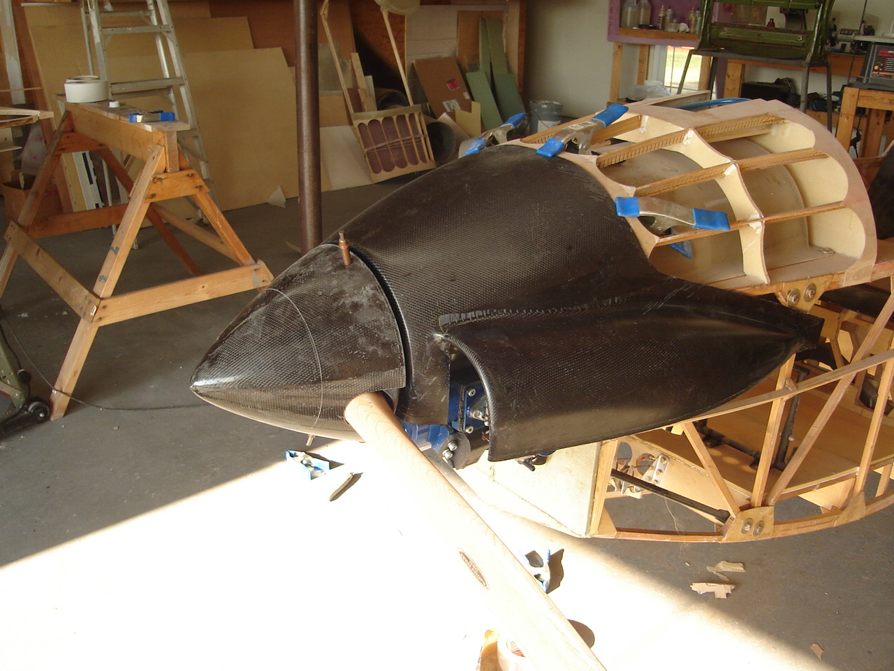
Carbon cowl

Well its been 35 days over 100 degrees and the old shop is a bit unbearable to work. I started sleeping after work and getting up at 9pm so I can work in the cool of the night. I'm making progress.I just finished fitting the spinner to the backing plate and trimming the spinner for the prop. I have the upper cowl trimmed and fitted.along with the  prop and spinner.
Spinner, ground adjustable prop and upper cowl
Upper cowl trim was previously determined by a fiberglass mock up cowl. I am using 7 oz graphite for the cowl because it is 10 times stiffer than fiberglass and can be laid up with only one ply. The edge bands got a extra doubler. The upper cowl, spinner and backing plate weighs 1lb 1oz.


view looking aft
I'm having a tough time finding metric 8mm x 1.25 grade 8 prop bolts with drilled heads. If anyone has a source please e-mail me at Planebuilder@yahoo.com


R/H side
So while its too hot outside to work, I have been working on a redesigned rudder pedal. I have a fixed seat, since the pilot can weigh as much as the plane, he must be positioned right in the center of the CG range. Consequently the rudder pedals must be adjustable. I had the opportunity 2 weeks ago to take an hour of aerobatic instruction in a ASK 21 sailplane, The rudder pedal adjustment mechanism is similar to an ASW 21 and is pretty typical of German sailplanes. Any way, if its good enough for them, its good enough for me.