Welcome to my Robin Blog.

It was suggested to me that I start a Blog on my ultralight project the "Robin". I have been working on this project for 4 years. On one of my first days at Vought aircraft, a stress man and future friend named Kenny Andersen walked up to me and said, "Aren't you the Mark Calder that designed the Wren Ultralight" Why yes I am I said. "well what have you done lately?" That was the genesis of the Robin design. The first 2.5 have been spent in the design phase. Actual construction started 1.5 years ago and has actually progressed smoothly. There have been a number of changes from the onset, but for the most part it is following my original concept. I will eventually sell plans for the Robin and make available all molded parts, fittings and welded assemblies. The Robin is designed to FAA part 103 and as such requires no pilots license to fly, although I think its a good idea to actually learn how to fly!! The actual name "Robin" was my Daughter Jamie's idea, I asked her to name the design based on my "cute little bird" theme (Wren)


Every good aircraft design has a "Mission" in mind before the actual design is started. A good designer will refer back to this mission every time a design decision must be made. Good design after all is just a series of good design decisions. On my first Ultralight design the Wren, the mission was to design a high performance low powered aircraft. The reduction of drag was the prime concern. I had been flying powered Hang gliders prior to this and because of this experience, I placed a high priority on climb performance. While most designers chose bigger engines, I chose lower drag and high aspect ratio (low span loading) wings. The Wren could out climb conventional Ultralight with up to 65 hp. The Robin follows this philosophy, but tries to improve on the performance of the Wren. Ultralight are not built by "rich" people, they offer an inexpensive means to enjoy one of the greatest experiences of my life, low speed soaring and flying.


Design Concept


The cost of an aircraft is directly proportional to its weight. , if low drag can be achieved then lighter and cheaper engines can be used. The Robin expands on the design mission of the Wren by using a longer span (40') wing and using a low speed laminar flow airfoil, (Wortmann FX 170) The leading edge of the wing on the prototype is molded fiber glass. The spar has been placed at 33% of the wing chord because the chosen airfoil is laminar over the first 32%. The aft covering is light weight Dacron Fabric. The leading edge of this fabric is purposely pinked and placed at the 32% chord point to facilitate laminar transition and elimination of separation bubbles. The main difference between the original design of the Robin and the current final design is the elimination of the single mono wheel retractable landing gear. Part 103 does not allow for a retractable landing gear. Which is really unfortunate because I spent a long time designing a really neat mechanism!!

In the course of the 4 years I have worked on the Robin, the structural design concept has evolved radically. Originally I was going to draw on the design of the Wren and use essential the same construction concepts. The original design of the Wren was heavily influenced by my Friend Steve Wood's Sky Pup design. I lived in Wichita Kansas and worked at Cessna Aircraft along with Steve. I watched his progress on the Pup and was very impressed with his concepts. I adapted the concept of using Styrofoam sheeting as the shear panels for the fuselage and the wing ribs. I did not however use the foam for the shear webs of the wing as Steve did. I originally wanted to build the fuselage of the Robin in a similar manner. Weight and the desire to not use foam for the basic structure due to the danger of fuel leaking eventually drove me to a all wood fuselage design. The wings were designed to take advantage of the Graphlite carbon pultruded material pioneered for the experimental aircraft by Jim Marske. I was familiar with this product from my experience at Bell Helicopter where it was considered in the construction of the V-22 wing.


Weight and Balance (unofficial roll out)

Well the weather finally broke, I sat inside working on my new wing redesign until I saw the first glimpse of the sun. I quickly gave my buddy Ed a shout and he came over to help me assemble the Robin out doors for the first time. This will be the longest Blog entry to date, there are a ton of pictures. Most were taken by Ed who showed me all the cool features I never knew the I-phone had!!

Farmer Ed
My Buddy Ed from down the street. He and I drove 3 weeks ago to Phoenix to buy the Mini Max project and my Ballistic Parachute, My chute is back to the manufacturer Second Chantz http://www.secondchantz.com/index.html  Getting repacked and re armed. I should have it back sometime next week. That is the only reason the fuselage is not covered. I need to route the riser straps outside of the longerons and around the main spar and landing gear. Give ole John Dunham a call and he will fix you up with a nice Ballistic Parachute!!


Front view
The wings have two coats of  Latex UV barrier paint. I was following the process outlined in the last blog entry. I have used a little over 3/4 of a gallon so far. I will easily be able to finish all of the fill and UV barrier coats on the is airplane for under 1 gallon. I am really impressed with this finishing method. It sure is cheaper than the certified water based systems. I had allotted 18 lbs of weight for the complete cover and finish. so far I am just under 5 lbs. This became really good news later in the day when I completed the weight and balance.


a man and his plane!!!


Here I am with my other friend


Me and Boo


Me and You and a dog named "Boo"


Left quarter view
 I'm pretty sure I will need a larger rudder.
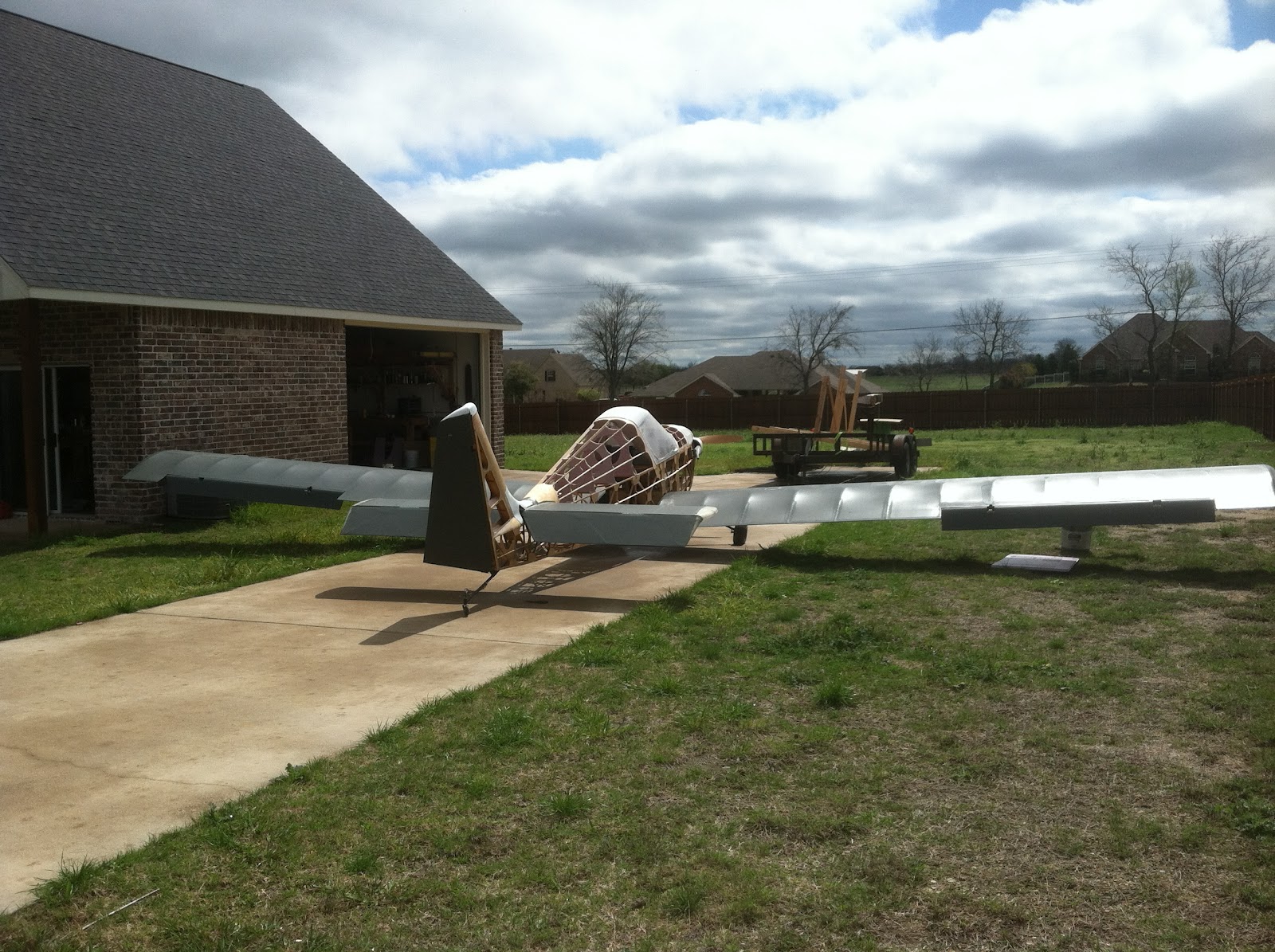


Right Rear Quarter view


looking down the L/H wing. We are getting set up for the weight and balance


Looking down the R/H wing


               L/H cowl view

My Friend Yuki Yoshi Ishihara of Chiba Prefecture Japan bought me this Propeller. I plan on Painting the words "Yuki's Prop" on it eventually. This is a CGS ground adjustable prop. It weighs 8.5 lbs. I will switch to a fixed pitch Spruce blade once I dial in the correct pitch. That will reduce my empty weight by 7 lbs.


 looking up


Exhaust side


I thought this was a pretty cool Picture Ed took.


leveling the Robin while Boo supervises
The plane was leveled and 3 scales were placed under the three wheels. The upper longeron is the level point.
Ed and I discovered a huge scale error under load. We spend some time calibrating the scales until we were assured they were accurate. That's what I get for buying $7.00 scales from Target!!


important first step!!!


Now this was a really important first step, literally!!! I rebuilt the inbd root leading edge of the L/H wing to add a walk way. It was solid as a rock!!


size 11's
You can see in this picture how 245 lbs is distributed over a fairly large surface area. The actual analysis however assumed I would place all of my weight on only one stringer. Over kill, but conservative and the step literally is rock solid.


An old designer once told me never to design for a skinny kid!! They never have any money!!

It is very comfortable in that cockpit. The profile of the seat is right out of a Jantar Ad in Soaring magazine. They claim its the most ergonomic seat shape ever designed. I believe them!!!

notice that the gear still has negative camber at full gross weight!!


Real Dummy


See if this Dummy looks just like


Fake Dummy


this Dummy!!!


(notice the gut)


Real Dummy again


The Jantar seat profile is really clear in this view. The Yarmulke really does its job. I definitely need to add some vents. It got hot really quick in that green house


Ed playing with his "Stick"

I asked Ed to work the controls and play with the Stick, I think he misunderstood me!!!!!

final weight and balance


So here is the end result of all of this fiddling around. I calculated the Neutral Point (NP) at 37.5% This is the point  around which all the aerodynamic forces are balanced. The center of gravity must be forward of the NP with a margin of safety Typically 10% to 15%

Well after all the sweating and sleepless nights here is the final numbers.
CG with no fuel  is 29.1% with a static margin of 8.2%

CG with fuel is 25.8% with a static margin of 11.5%

this is a good link to an online calculator   http://www.geistware.com/rcmodeling/cg_super_calc.htm

This is as close to perfect as I ever thought I could get. Now for the best news, the plane weighs 262 lbs with the 7 lbs extra weight prop hub. and with parachute it will weigh 276 under the 284 FAA part 103 weight allowance allowed for a Ballistic chute. With the light prop the empty weight will be 255lbs. The new wings will be at least 30 lbs lighter, that and some other weight improvements will easily allow for brakes and a starter on plans built planes.


Latex House Paint Covering method.


Big milestone today. I started finishing the fabric. I decided a while ago after some research that the Latex house paint system was the lightest covering method I could use. The major covering methods are mostly dissolved thermoplastic. All of these processes are heavy. The latex system I believe is also similar to the Stewart covering system,  http://www.stewartsystems.aero/default.aspx    in fact I am using their adhesive called Eco Bond. There has been a ton of research done on using Latex House paint. A friend of mine in Wichita, Duane Life covered  his J3 Kitten and I have always been impressed with the finish. A lot of good work and research has been done on this process, the most impressive is Drew Fidoe's blog http://www.bowersflybaby.com/tech/latex.html, other good sites are the reprint of Charles Threewit's article http://www.lazair.com/housepaint.htm   and this article in Ultralight News http://www.ultralightnews.ca/articles/housepaint.htm

Fresh Bloom
The process starts with a good base latex Acrylic latex enamel. I am using Sherwin Williams D-100 gloss exterior enamel The base color of my Robin based on my Friend Bills design is Gun Metal Grey. This may be too dark, so after the base UV coat is applied I may pick another lighter color if Bill decides I need it. The formula for using latex involves adding a viscosity modifying agent called Floetrol. This smooths out all brush and roller marks. Each coat is additionally thinned with standard windshield wiper fluid. The links give the ratios. 

The day started nicely with a fresh bloom in the flower box.  We had a few  85 degree days last week. Like I said earlier, Texas is wonderful in the spring, winter and fall!!!


I started with the ailerons. I figured they were the easiest to recover if I screwed up.

Single coat on Ailerons
 The procedure for finishing goes like this. After the paint is well thinned and mixed with Floetrol. it is rolled on with a foam roller. Right behind the roller you follow up with a foam  brush and push the first coat into the open weave. Let that dry and and complete the same process on the opposite side of the part you are working on. The second coat is put on with only the roller and is rolled 45 degrees in the opposite direction of the first coat.


Ed doing the Brushing duties


 Its amazing how well this covers. By the end of the day, all of the control surfaces and Horizontal were finished and I had used less than a quart of paint. The beautiful thing about that is its mostly water and it evaporates away.


Ailerons with second coat
 Depending if Bill likes this color, the next step will be a spray over coat at Eds house in his spray booth. At this point the fabric on the surfaces sounds like  a snare drum when you tap it. Its pretty exciting seeing it at this stage. 


Coating the elevator

 This is me doing the elevator. I tried to measure the weight gain at this point, but I found that my scales were not sensitive enough to measure the difference. I will know exactly when I reassemble everything an re weigh, but from the looks of it my weight gain will be measured in ounces. My estimate of the paint weight was 12 lbs. Based on that I was going to be 10 lbs over weight. 


Finished Rudder
 The Rudder was recovered after the trailing edge was replaced. Again, I could not measure any weight gain.


Wings
 This is another view that shows the wings. They came out beautiful!! Over weight , but very clean and smooth.


Horizontal with one coat

 The Horizontal came out beautiful. Its very smooth and very clean. I can hardly wait to fly this thing.
Parachute trip, revised rudder and covering.


So its been a very busy 3 weeks. I have been traveling on my job and last week end my friend Ed and I drove to Phoenix Arizona to buy a Mini-Max project, I was looking for a Second Chanz 550 or 600 ballistic parachute, This particular model weighs 13 and 17 lbs respectively. Because of the 30 lb weight allowance the FAA allows, this particular model will give me the 10 lb margin that the prototype appears to be overweight. I found a project for sale and one of the items was a model 600 ballistic chute. I called my Buddy Ed Gardner and asked him if he wanted to split the whole deal, he gets the complete project, I get the parachute. The final price was a really good deal, circumstances combined to force Mike Gurtler to part with his project.
Mike and his old Project

I got to hand it to my Friend Ed, he had a really good idea about how to pack the project, he bought 2 foot wide packing wrap, similar to Saran Wrap. We covered each section three times. That turned out to be the perfect number. We hit nasty weather coming back thru the mountains near El Paso. On the following day (Sunday) we were in ice, rain and snow all the way to the Dallas Fort Worth area

We spent about 2 hours packing the project in Phoenix.


Mike and me just before shove off
Ed and I drove my old 96 Chevy Z71 Pick Up. (219,000 miles)  I have had this truck since it was new and I have religiously maintained her,but 2 years ago I had to put in a new transmission. Other than that I have not touched her. I attribute her long life to the use of Mobil 1 oil . Anyway, she made the trip


ready to shove off
We both got one hell of a deal, I got a $3200 parachute and Ed got an airplane complete with all covering materials , engine and a brand new composite ground adjustable prop. I wont mention the price, but our gas was just about equal!!!
I accused Ed of being really anal when it came to packing up the project, well that turned out for the better, he decided to do one last walk around through Mikes garage and guess what!! There was my parachute sitting on top of a trash can!! That was the whole reason I bought half of this project. It would have been near impossible to ship the chute to me once I had left. The pyrotechnic would have to have been removed.

 I finished my Wing Walk and started covering the L/H wing. I then went back to the rudder. Turns out I designed the trailing edge too light. After I covered the rudder I noticed the trailing edge was scalloping and the fabric was losing its tension.


wing walk skin installed
This picture shows the wing walk after installation. The outer glass surface has been scuff sanded.


using the Multi-tool to cut off the training edge
So I used my muiti-tool to cut off the trailing edge. as you can see in this photo, its only .125" thick and .75" wide. This was actually unstable in torsion. After the fabric was shrunk, the trailing edge rolled over. I am modifying the trailing edge to be similar ti the rest of the airplane. I will detail the Trailing edge attachment in the next blog.

I prepped the L/H wing for cover, but will not actually be able to cover it until Tomorrow.
I tried to mount my new Ballistic parachute and discovered that due to the wing being overweight, I cannot mount the chute behind the pilot (at least not now) The weight and balance right now was the rear limit at 30% with no fuel and 22% fwd CG with full fuel. Still working on the chute installation. I am thinking that I will mount the wings after cover and then check the final balance. This will determine where the parachute goes
Wing Walk and some test photos.


I started modifying the L/H wing to reinforce the leading edge so I could add a wing walk. The redesign was pretty straightforward. I removed the existing wing skin with my multi-tool. That thing zipped right through the fiberglass. After the skin was removed, I reinforced the foam ribs with a ply of 8 OZ fiberglass on each face of the exposed ribs.
lateral stiffeners

I then slotted the ribs every 2 inches and inserted a wooden stringer. the Stringer was sized to react 250 lbs between the farthest span (6") so basically each stringer can support the weight of one step. In reality the load will be distributed between at least 3 members. The stringers were potted in with micro balloon and epoxy. Using the leading edge lay up mold, I laid up a 2 ply skin of .012 thick carbon fiber.


leading edge walkway skin

2 ply's of graphite and a single lightweight ply of glass comprise the walkway skin. The leading edge was taper sanded  to allow blending into the existing skin.


Right now the skin is curing after having been bonded 8 hours ago. Tomorrow I will be able to flip the wing over and finish sanding the skin in preparation for covering. I should be able to finish the covering tomorrow.


rib stitching
My airfoil is a Worttman 170 low speed laminar flow airfoil. It has a reflexed trailing edge on the upper and lower surface. Because of this, the fabric tension after shrinking will try to pop off the reverse curve surface. So I elected to rib stitch the trailing edge where the reflex is. Everywhere else on the wing, the fabric is bonded.


wing re test
The original wing test spar has been sitting out in the weather for over 2 years. The ultra violet radiation has attached the foam and the fiber glass. Periodically I retest the wing. The original wing was rebuilt after initial destruction testing and re mounted to the back side of my test stand. A 2 x 10 wood extension was added to increase the applied moment such that it equals the actual moment on the wing. This is a little conservative because the wood does not deflect similar to the wing. Because of this the stress is concentrated more toward the root, there is no relief that would normally occur it the complete wing was allowed to deflect.


anyway, this is a picture of the wing at just a little over limit load. There is 1200 lbs of force being applied. In the previous picture you can see my load cell that I designed. I made a piston with exactly 1 inch of area. I then bored a cylinder out of some scrap aluminum.I drilled and tapped into the cylinder and installed a 3000 psi pressure gauge. I filled the void with transmission fluid. The actual load now is a one to one read out. I calibrated the load cell at work on a universal testing machine one day at lunch. There is a little hysteresis error, but that was under 100 lbs. Close enough!!!


New Paint Schemes

My Friend Bill Dale came through in spades, he laid out a number of design possibilities. I have chosen the one shown in the header, but here were other possibilities. Unfortunately I have been traveling again and have not made as much progress as I would have liked.


Covering part 2 (R/H wing) additional pictures

This is just a quick update, I have the bottom surface of the wing covered. one area I discovered that could be a problem with bonded skin, is the aft portion of the lower surface of the main rib. There is a reverse curve or cusp at the Trailing edge. When the fabric is shrunk, there will be a tendency for this area to pull away.if it does, I will rib stitch the aft portion of every rib, but in the mean time I decided to add two cloth tapes on the inside of each rib. This should react the cleaving or pulling forces.

shear webs
the lower surface was added first, this allow for a overlap of the upper surface fabric such that the seam faces aft.

the lower fabric has only been partially shrunk @250 degrees. after the upper surface is on, both surfaces will be final shrunk to 300 degrees.


Fwd Fairing covered

The fwd fairing came out really nice.
I have some repair work to do on the L/H wing and then I will cover it. The Fuselage is last, everything else is covered.


R/H wing top view
 both upper and lower surfaces are covered. Cable exit doubler is shown in this view, Tomorrow I will rib stitch the lat 12" of the inboard 6 ribs. this is required because the curvature of the airfoil reverses and tension on the fabric could pull the fabric off.


 view looking down the wing. i'm very pleased how smooth the wing is after cover.

covering part 1 (Tail Feathers)

I started covering the tail surfaces. The rudder was first. This is the first time I am using the Stewart system Eco Bond adhesive. As usual there is a learning curve to go down. I will eventually re-cover the rudder, but I learned a few good lessons. The Eco bond is really good stuff, but it needs to be applied with a foam brush. The natural fiber paint brush I was using does not apply the adhesive evenly. This will make for a lumpy covering job. In the Stewart manual, they give a lot of good tips, one of them was the use of this disposable cup method.
Chinette plate and Dixie cup holder

this is a holder for the Eco bond adhesive. In the middle is a cut down Dixie cup that has been bonded with 5 minute Epoxy to the center of a Heavy duty Chinette paper plate. A fresh Dixie cup is used for the actual adhesive. Its placed in the Dixie Cup holder. This way it wont spill on you. about 1/3 a cup is all the adhesive you work with at a time. That's the length of out time you have available.
The Eco Bond is water soluble, but once it cures, its set for good.


pre coating the structure

The method I finally settled on is to pre-coat the entire structure and let it fully dry. The Eco Bond is heat activated. The fabric is placed into position and then ironed onto the frame with a iron set and calibrated to 200 degrees. The heat of the irons is extremely important. Its very important to use a good IR thermometer when you calibrate the Irons. The normal main shrink temp is 250 degrees, on a certified plane with heavier structure, the shrink is accomplished in three steps, 250 degrees, 300 and finally 350 degrees. that is way too much for an ultralight airframe.  This is the main reason I am recovering the rudder. I used the higher temp and I bent the trailing edge. Its slightly scalloped. All ultralights stop the shrink at 300 degrees.
Rudder
I am using a single wrap piece of cloth for the rudderThe first wrap will attach to the trailing edge The cloth will be wrapped over the trailing edge. The opposite side will wrap over the railing edge and attach to the cloth only. All ribs are also bonded,


Ribs being bonded
 once the adhesive dries, the fabric is tacked on using a heated iron, after everything is in place, additional Eco bond is brushed into the surface to adhere to the previous coat. Once this sets, its really on there.


beginning of the Horizontal

The horizontal came out really well. I used two separate pieces to cover this surface. Both pieced will over wrap the leading edge.


Finished Horizontal

So far the covering process added only 2.5 ounces, the real weigh gain will be the finish. Tomorrow I will finish the elevator and the ailerons. My buddy Ed will come by tomorrow and we will pull the wings. I can cover the R/H wing immediately, the L/H wing needs some repair on a plywood piece that was damaged during storage. But I should have both wings covered by Saturday. Then its on to the fuselage. after I cover the fuselage and finish the plane, I need to re assemble the wings and then build a root fairing. I decided it would be easier once I figure out where the fuselage fabric is placed.