Welcome to my Robin Blog.

It was suggested to me that I start a Blog on my ultralight project the "Robin". I have been working on this project for 4 years. On one of my first days at Vought aircraft, a stress man and future friend named Kenny Andersen walked up to me and said, "Aren't you the Mark Calder that designed the Wren Ultralight" Why yes I am I said. "well what have you done lately?" That was the genesis of the Robin design. The first 2.5 have been spent in the design phase. Actual construction started 1.5 years ago and has actually progressed smoothly. There have been a number of changes from the onset, but for the most part it is following my original concept. I will eventually sell plans for the Robin and make available all molded parts, fittings and welded assemblies. The Robin is designed to FAA part 103 and as such requires no pilots license to fly, although I think its a good idea to actually learn how to fly!! The actual name "Robin" was my Daughter Jamie's idea, I asked her to name the design based on my "cute little bird" theme (Wren)


Every good aircraft design has a "Mission" in mind before the actual design is started. A good designer will refer back to this mission every time a design decision must be made. Good design after all is just a series of good design decisions. On my first Ultralight design the Wren, the mission was to design a high performance low powered aircraft. The reduction of drag was the prime concern. I had been flying powered Hang gliders prior to this and because of this experience, I placed a high priority on climb performance. While most designers chose bigger engines, I chose lower drag and high aspect ratio (low span loading) wings. The Wren could out climb conventional Ultralight with up to 65 hp. The Robin follows this philosophy, but tries to improve on the performance of the Wren. Ultralight are not built by "rich" people, they offer an inexpensive means to enjoy one of the greatest experiences of my life, low speed soaring and flying.


Design Concept


The cost of an aircraft is directly proportional to its weight. , if low drag can be achieved then lighter and cheaper engines can be used. The Robin expands on the design mission of the Wren by using a longer span (40') wing and using a low speed laminar flow airfoil, (Wortmann FX 170) The leading edge of the wing on the prototype is molded fiber glass. The spar has been placed at 33% of the wing chord because the chosen airfoil is laminar over the first 32%. The aft covering is light weight Dacron Fabric. The leading edge of this fabric is purposely pinked and placed at the 32% chord point to facilitate laminar transition and elimination of separation bubbles. The main difference between the original design of the Robin and the current final design is the elimination of the single mono wheel retractable landing gear. Part 103 does not allow for a retractable landing gear. Which is really unfortunate because I spent a long time designing a really neat mechanism!!

In the course of the 4 years I have worked on the Robin, the structural design concept has evolved radically. Originally I was going to draw on the design of the Wren and use essential the same construction concepts. The original design of the Wren was heavily influenced by my Friend Steve Wood's Sky Pup design. I lived in Wichita Kansas and worked at Cessna Aircraft along with Steve. I watched his progress on the Pup and was very impressed with his concepts. I adapted the concept of using Styrofoam sheeting as the shear panels for the fuselage and the wing ribs. I did not however use the foam for the shear webs of the wing as Steve did. I originally wanted to build the fuselage of the Robin in a similar manner. Weight and the desire to not use foam for the basic structure due to the danger of fuel leaking eventually drove me to a all wood fuselage design. The wings were designed to take advantage of the Graphlite carbon pultruded material pioneered for the experimental aircraft by Jim Marske. I was familiar with this product from my experience at Bell Helicopter where it was considered in the construction of the V-22 wing.


Weight and Balance (unofficial roll out)

Well the weather finally broke, I sat inside working on my new wing redesign until I saw the first glimpse of the sun. I quickly gave my buddy Ed a shout and he came over to help me assemble the Robin out doors for the first time. This will be the longest Blog entry to date, there are a ton of pictures. Most were taken by Ed who showed me all the cool features I never knew the I-phone had!!

Farmer Ed
My Buddy Ed from down the street. He and I drove 3 weeks ago to Phoenix to buy the Mini Max project and my Ballistic Parachute, My chute is back to the manufacturer Second Chantz http://www.secondchantz.com/index.html  Getting repacked and re armed. I should have it back sometime next week. That is the only reason the fuselage is not covered. I need to route the riser straps outside of the longerons and around the main spar and landing gear. Give ole John Dunham a call and he will fix you up with a nice Ballistic Parachute!!


Front view
The wings have two coats of  Latex UV barrier paint. I was following the process outlined in the last blog entry. I have used a little over 3/4 of a gallon so far. I will easily be able to finish all of the fill and UV barrier coats on the is airplane for under 1 gallon. I am really impressed with this finishing method. It sure is cheaper than the certified water based systems. I had allotted 18 lbs of weight for the complete cover and finish. so far I am just under 5 lbs. This became really good news later in the day when I completed the weight and balance.


a man and his plane!!!


Here I am with my other friend


Me and Boo


Me and You and a dog named "Boo"


Left quarter view
 I'm pretty sure I will need a larger rudder.


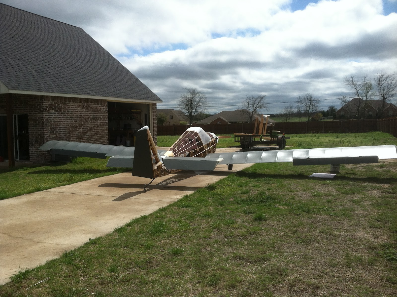
Right Rear Quarter view


looking down the L/H wing. We are getting set up for the weight and balance


Looking down the R/H wing


               L/H cowl view

My Friend Yuki Yoshi Ishihara of Chiba Prefecture Japan bought me this Propeller. I plan on Painting the words "Yuki's Prop" on it eventually. This is a CGS ground adjustable prop. It weighs 8.5 lbs. I will switch to a fixed pitch Spruce blade once I dial in the correct pitch. That will reduce my empty weight by 7 lbs.


 looking up


Exhaust side


I thought this was a pretty cool Picture Ed took.


leveling the Robin while Boo supervises
The plane was leveled and 3 scales were placed under the three wheels. The upper longeron is the level point.
Ed and I discovered a huge scale error under load. We spend some time calibrating the scales until we were assured they were accurate. That's what I get for buying $7.00 scales from Target!!


important first step!!!


Now this was a really important first step, literally!!! I rebuilt the inbd root leading edge of the L/H wing to add a walk way. It was solid as a rock!!


size 11's
You can see in this picture how 245 lbs is distributed over a fairly large surface area. The actual analysis however assumed I would place all of my weight on only one stringer. Over kill, but conservative and the step literally is rock solid.


An old designer once told me never to design for a skinny kid!! They never have any money!!

It is very comfortable in that cockpit. The profile of the seat is right out of a Jantar Ad in Soaring magazine. They claim its the most ergonomic seat shape ever designed. I believe them!!!

notice that the gear still has negative camber at full gross weight!!


Real Dummy


See if this Dummy looks just like


Fake Dummy


this Dummy!!!


(notice the gut)


Real Dummy again


The Jantar seat profile is really clear in this view. The Yarmulke really does its job. I definitely need to add some vents. It got hot really quick in that green house


Ed playing with his "Stick"

I asked Ed to work the controls and play with the Stick, I think he misunderstood me!!!!!

final weight and balance


So here is the end result of all of this fiddling around. I calculated the Neutral Point (NP) at 37.5% This is the point  around which all the aerodynamic forces are balanced. The center of gravity must be forward of the NP with a margin of safety Typically 10% to 15%

Well after all the sweating and sleepless nights here is the final numbers.
CG with no fuel  is 29.1% with a static margin of 8.2%

CG with fuel is 25.8% with a static margin of 11.5%

this is a good link to an online calculator   http://www.geistware.com/rcmodeling/cg_super_calc.htm

This is as close to perfect as I ever thought I could get. Now for the best news, the plane weighs 262 lbs with the 7 lbs extra weight prop hub. and with parachute it will weigh 276 under the 284 FAA part 103 weight allowance allowed for a Ballistic chute. With the light prop the empty weight will be 255lbs. The new wings will be at least 30 lbs lighter, that and some other weight improvements will easily allow for brakes and a starter on plans built planes.