Pages

Engine cowl part 3 (Cheek cowls).

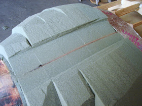
The next step in the construction of the master model was fabrication of the cheek cowl cores. The Robin is a loose copy of the Fournier RF4D Motor glider. This plane was originally powered by a  flat 4 cyl. VW Limbach conversion. as such it had two side cheek cowls that streamlined the cylinders. On the Robin, I am using an upright single cylinder 2 stroke. I decided to retain the cheek cowls because they serve two purposes, they will streamline the carburetor and the air filter and streamline the exhaust. At this point in the construction of the engine cowl, I have completed the main body of the cowl and fared the firewall to the spinner. The main cowl is shaped, a layer of fiberglass was added and a light milk coat of body filler was added. I began construction of the Cheek cowl by laying out the surface loft on my 3D cad system. I plotted the plan view and section cuts space exactly 3" apart. I transferred the loft to some Masonite and cut out all of the templates.      
R/H Cheek cowl Patterns.
        
1/8" Masonite was used for the templates. The original pattern was plotted on printer paper and 3M 777 spray adhesive was used to affix them. do not use water based adhesive for this step, the paper will swell and distort. at some point the contour reverses and the same template is used for the fore and aft position.


Cowl template in position


I trial fitted the template at this point to ensure I had enough excessive flange area. As shown in this view, more tape had to be added above and below the cheek cowl. The actual part will only be a 1 inch flange beyond the cheek cowl, but excessive edge is needed for the building of the lay up tool and plaster splashes.

foam being sanded flush on the belt sander


All of the templates were lightly tacked to the foam with 5 minute epoxy of bondo. just a small dab is all that is needed, because the template is removed later. The foam is rough cut on the band saw and then flush sanded on the belt sander .


templates being bonded

the foam had to be pieced together for the larger templates. a small bond was all that was needed and it was placed such that it was buried inside the final contour.


foam blocks in place on master template


The foam was bonded with a very small dab of bondo to the master template. I want to remove the foam later after it has been shaped. in this view, the plan view off the foam was sanded flush to the template.

Top surface was sanded tangent to the foam blocks

In this view the sanding stick was used with 36 grit paper to sand the top surface tangent to the foam. The surface is sanded until the edge becomes a line.


corners sanded tangent
the same sanding stick was used to sand the corners flush. At this point the foam can be final shaped using a block of scrap foam as the sanding block

.

as you can see the results are excellent!!!


Foam shown during final shaping.
By sanding the foam with the foam, both pieces abrade each other. the result is a beautiful spherical interface. This surface is wave free and readily finishes after a layer of fiberglass is applied.


Another view of the final surface


After the foam was shaped I was able to peel the main template off without damaging the foam.


36 grit sandpaper tacked to the cowl


After the cowl was formed, it was necessary yo contour the base so it would fit flush to the engine cowl. I hit on the idea of sanding the contour into the foam cheek cowl cores. It worked like a charm!!!


cheek cowl bonded into position

After the cheek cowl was fit to the main cowl, it was bonded in place. The next step was to lay one layer of 8 oz fiber glass on the foam so I could complete the finishing. this is urethane foam, so any suitable laminating resin can be used. Because of cost and time considerations I used polyester resin. The cure was complete in 45 minutes.


L/H cheek cowl/inlet


The L/H cheek cowl was fabricated similar to the R/H cheek. The main difference is the addition of a cooling air inlet.

the cowl was also sanded into position and later attached.
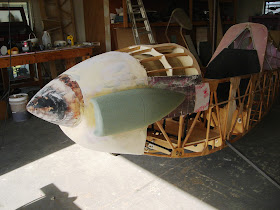
L/H cowl in position


As I write this update i have completely coated and block sanded the cowls. I have added blend fillets between the cheeks and the main cowls.


The final finish and removal of the cowls is the subject of the next Blog.

Engine cowl part 2


lower Foam blocked in place

The lower half of the foam shaping started by flipping over the fuselage.


I want to thank my Friend and neighbor Ed Gardner for all of his help on this one. He's a pretty big boy, airplane nut and an all around good guy!!
check out Eds project and Business: http://mmwauto.com/index.php/services.html

As shown in the upper cowl blog, the foam was fitted between the firewall and the 1/4" foam space that was attached to the rear of the spinner mold.

Again the rules for attaching the foam is to make sure the glue is well below the final contour and that internal cut outs are also below the final contour. Its not a disaster if they are, as you will see later, I ended up with a small hole.

Another view of the blocked in foam

After the foam is blocked in, I started the initial shaping. rough cuts were made with hand saw and final cuts were made using a sanding foam block with 36 grit paper. I have made other cowls before using higher density urethane foam, the result is similar, but the higher density just takes a lot longer to shape.


rough shaping with a hand saw.


I first hit on this idea of using floral foam when i built a cowl for an abandoned project you sometimes see hanging on my wall. I used to build a number of sail plane models and the nose cone was always carved out of a block of Balsa. The carving technique was always to profile the plan view and then the side view. after that the rest was sanded away. I found out about Telescope hobbyists using glass to grind glass and I realized that floral urethane foam would do the same. This really works quite well.
More rough cutting

You will notice in this picture that the center line template was exposed by sanding. I use 36 grit paper when I do this. There is no need to use any finer, it only slows down the process. The side templates will also be sanded to profile the plan view.


Final shaping

After the rough cuts were made, scrap pieces of the foam were used to finish the final sanding. as you can see there is a small hole in the foam, I'm not worried about this because the next step is to lay a layer of fiberglass and eventually fill and fair the surface with Bondo or Automotive body filler.


Another view of the final shape

I continued to 'tweek" and fine tune the shape for a little while after this. Once the basic shape of the main cowl is finished, I will start the process of adding the cheek cowls. These cowls will be assymetrical, The R/H cowl will be the fairing for the exhaust and the cooling air outlet. The L/H cowl will have an air inlet and also fair the carb and air filter.

Side profile before fiberglass is applied


Before fiberglass is added, the surface is prepped with a mixture of resin and Micro Balloon. The Micro is added to about 4 OZ of resin and mixed to the consistency of pancake batter. The purpose of this is to fill the open cells of the foam. If you do not fill the cells, the laminating resin will eventually wick into the cells and draw air into the laminate.

One layer of 8 OZ cloth added

Here is a picture of the cloth overlaid on the foam. I use the 8 oz Rutan style BID cloth. This is a 8 harness crowfoot weave style cloth. It is extremely drapable and will conform to almost any contour. I added layers of aluminum tape so I can have an excessive flange. This will be important later in the mold process. The tape on the side will be in the location of the eventual cheek cowl. A couple of plies of Peel ply were also laid at the lower edge of this lay up. They are removed before the upper surface is laid up. They allow a smooth transition and a bond able surface when peeled off.

Initial coats of Bondo applied
 The process was repeated for the upper surface and the first layers of Bondo were added. The idea on the bondo is to completely coat the fiberglass to hide and of the weave and to smooth out any small waves in the surface. I will not completely finish out the master at this stage, I still have to add the cheek cowls.


View looking aft
 This is a good view of the upper and lower surfaces. I didn't have to spend a great deal of time finishing the sides in the areas of the cheek cowls.


Ready for the Cheek Cowls.

The next step is preparation for the cheek cowls. I'm going to try something I have never done on this step. I will build up the cowls on the bench similar to the way I have done my wing tips. I will then remove the cowls from the backing board. I plan on temporally gluing some sand paper to the fuselage and then sand the contour into the cheek cowls.

That's the next blog entry.

Engine cowling

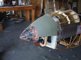
The building of the cowl started by mounting the spinner master model into position on the prop hub. as previously mentioned, I designed this master model with a 1' diameter hole that aligned with the 1" prop hub flange. After the spinner master was in position I constructed  4 templates and mounted them internally. These templates represented the side inboard profile, and the max half breadth of the plan view. Masonite templates were first fitted and then a splining stick was used to fair  the curves from the fuselage to the spinner. These will become sanding guides later in the process. as I mentioned earlier, I am using 1lb/ft cu floral urethane foam. Its important that you buy enough to finish the first time. My experience is you cannot mix manufactures or different production batches. I bought all of this foam from  Hobby Lobby. They had a new larger sheet product that I am using for the first time. I swear every time I buy a large batch of this foam the cashier thinks I am a gay florist!! I am outlining this process to show how I make these molds without the use of a NC router. These steps will not be necessary for a plans builder because I will have all of these molded parts available. The process is interesting however!!
foam being fitted
After the templates were mounted small gusset blocks were made to lock each of them together. In this picture you will notice a blue/green sheet of 1/4" PVC foam that was bonded to the back side of the spinner master. This is a spacer to ensure a gap between the cowl and the spinner.

 All of the supporting structure and the eventual sanded foam blocks are designed to slip off the front of the engine after they are shaped and a layer of glass is added. The surfacing of the cowl will be done while it is attached. This will all be later removed and plaster splashes will be taken of the plug master. the cowling will be split horizontally through the center line of the prop hub. In addition to the actual cowling, there will also be two "cheek" cowls added after the finishing operation.

Blocks of foam are fitted to the templates. Care is taken to ensure the internal foam is cut out to clear the engine when the plug is removed.
upper foam in place

 All of the foam for the upper half is in place. if you have any gaps, stuff wedges of the foam to fill these voids.


initial shaping begins
 After the foam is in place, the initial shaping begins. I try to cut within a 1/2" to the horizontal and vertical templates. any tool will do, I used a hack saw blade and a small hand saw. Do under cut into the foam.  I doesnt hurt to stand back and look before each cut.

Vertical template sanded to the edge
 The next step is to sand with a sanding stick down to the template edge. Hold the stick perfectly level when sanding the vertical template and hold the stick vertical when sanding the horizontal templates. This is so you avoid undercutting the contour.


initial shaping of the foam

After the templates are sanded to the edges, you can start to carve away the foam in between them. Use a saw or a butchers knife for this. Do not over cut, be very generous at this stage. Once the foam is trimmed, the real magic of this process happens. Scrap foam blocks are used to sand the foam. Both materials will equally abrade each other and transfer the contour back and forth. This creates a spherical interface and it is the same principal that Telescope hobbyists use to grind their lenses, they use glass to grind the glass.
L/H view


Here is the final outcome of the foam shaping. This is a beautiful wave and dimple free surface the cleanly blends between the firewall and the spinner. The "P-51" look of the nose is now evident.


Next is the bottom surface. That will be the next blog entry


Front spinner, mold and cowl

I am just starting to build the front cowl master model. The process stated with the construction of the Spinner master model. The spinner surface was designed to allow the cowling loft lines to blend in the side profile and the top or max half breadth profile to the rest of the fuselage. consequently its oversize from the typical spinner one usually sees on an ultralight or conventional airplane. I took the surface loft directly from my 3D model and intersected it with planes spaces 3/4" apart. I then plotted all of them out together and made a plot of the combined stack up. I also plotted a 1" diameter hole in the center that was common to each section. This was to allow all of the sections to be aligned on a 1" diameter tube. I cut all of the sections out from a sheet of MDH board. I stack glued them together and then mounted the stack up on my lathe. 
MDH sections bonded and mounted on a face plate
                                                                            MDH board is a good material to use for this master model, it is basically pressed sawdust and because of this it has no grain direction. It will smooth and work evenly in all directions. The stack up was mounted to an aluminum face plate to allow me to chuck it onto the lathe. I stated turning the stack up. The actual loft contour line is at the bottom of each circle.


spinner master being turned down

I set up a tool fence on my metal lathe similar to that used on a wood lathe. I worked the stack up using conventional wood lathe chisels. This was a relatively quick job. It wasn't long before the final shape started to emerge.


Master after sanding and before a coat of Bondo.
 At this point the surface had to be coated with a light coat of Automotive body filler or "bondo" to fill in all of the surface pores and to allow for the final smooth finish.


Master with a surface coat of Bondo
 After the Bondo was applied, it was sanded down smooth. Subsequent coats were added and each time a finer and finer grit of sand paper was used. Eventually the surface was painted with sand able primer and then further filled with spot putty. The final surface was sanded with 400 grit sand paper and a top coat of urethane automotive paint was applied. From this "plug" or Master model I then made a female mold. At the same time I built the Spinner mold I also made the Horizontal/Elevator tip cap mold. It was more efficient to shoot the Gel coat when I had a second mold to produce.

Spinner and Horizontal Tip cap molds.


Both of these molds will be wet sanded with 600 grit paper and then "seasoned" with up to 12 coats of carnuba mold release wax.


As I mentioned earlier I made the original Spinner plug with 1" diameter holes to use for alignment. The secondary purpose of this was to allow the original plug to be temporally mounted to the engine prop flange So I can start the shaping process of the  cowl master model. I will again use my floral foam method to shape the cowl surface. There will be a sub frame built to support the foam blocks while they are shaped and to eventually allow the foam master to be slipped off the fuselage so a plaster splash can be taken. Here is a picture of the spinner in place before the foam is added. 
Spinner Master attached to prop flange


2 stroke exhaust design and build

The stock muffler that came with my MZ 34 was not suitable for my design. Besides being  the wrong configuration, it weighed 4.8 lbs and was not tuned. I talked to Leon Massa of Compact Radial engines and he told me that the design is conservative and not designed to any specific power band. Due to the configuration I chose for the Robin, the exhaust must exit the engine and turn 90 degrees aft.  I am emulating the cheek cowls of the original Fournier RF4D which was powered by a Limbach VW conversion. That engine is a flat 4 cylinder.  Its ironic, but a single cylinder 2 stroke engine is actually wider than it is tall. I do not like the ultralight designs that have the pipe just hanging in the breeze. I wanted to design the cheek cowls such that it would streamline the carburetor and air filter and the the exhaust. I plan on ducting the cooling air into the L/H cowl and flow it over the head and then let it exit out the R/H cowl. Because of this, the cowls will be slightly asymmetric.  Another side benefit is that the cheek cowl will act as a secondary sound barrier for the case borne noise of the exhaust. Most sound from a two stroke engine originates from the exhaust. This is one of the reasons why its desirable to have a completely round cross section. This eliminates flat areas that will resonate and crack. Cracking is a huge concern on this pipe, because of this I am using the original spring suspension and I have incorporated two small rubber shock mounts. The exhaust will have a large freedom of movement to allow it to move with the engine during idle. 
pipe shown in mounting position


I had my first introduction to the benefits of a tuned exhaust with the first prototype of my Wren. I flew the original prototype with a 22HP Xenoah engine. All I had for an exhaust was a short length of flex tubing. The prototype in this configuration was terribly underpowered. One day I was flying south east of Wichita near Rose Hill. I was flying parallel to some huge power lines when the engine started to sputter.  I had no choice but to turn away from the lines and set down in a freshly cut wheat field.  As I was rolling out on landing a young kid on a 2 stroke motor cross bike came out to meet me. I immediately apologized for landing in his field. He told me that he thought I saw him wave to me and motion me to land? I again apologized and said I hadn't. He said he wanted to meet me and tell me that my engine was running really rich and was "4 stroking" as it ran. He then proceeded to tell me that I needed a tuned pipe really bad. I looked at his bike and it was obvious he had made the pipe for that bike. I asked him if he knew how to make a tuned pipe? "Of course" he said. We rolled the Wren into his dad's barn and set about designing a tuned pipe. We had to partially disassemble the engine to determine the timing of the intake and exhaust ports. He set up a degree wheel on the crank and we recorded the exact point the exhaust port and intake port opened and closed. The timing and design of the pipe starts from the point the exhaust port opens. Here is a picture of what my new pipe looks like. 
straight pipe before elbow was added
                                                                       A modern tuned pipe consists of an expanding section, a constant section and a diffuser or tapering section. The final section is an outlet stinger pipe. The process starts with the exhaust pulse, it is quite powerful and travels approximately at the speed of sound. All of the pipe section geometry are based on the speed of sound and the time it takes a wave  to travel . As the first pulse leaves the exhaust port and travels down the first expanding section, the piston continues its downward power stroke, When the original pulse reaches the end of the first tapered section, an inverted negative pressure wave is created. This wave in turn travels back up the first expanding section and as it does it increases in intensity due to the constriction of the tapered section. This negative pressure pulse arrives back at the exhaust port at the exact time that the intake port opens. This negative pulse has a scavenging effect that serves to draw in a new fresh air-fuel charge. This pulse is so strong that it actually pulls the fresh charge out of the cylinder and into the expanded exhaust section. Meanwhile the original power pulse has traveled the length of the constant section and has arrived at the diffuser section. This has the effect of creating a very strong positive wave that again travels back up the exhaust toward the exhaust port. It arrives and actually pushes the fresh fuel air charge back into the combustion chamber. By this time the piston has traveled to the point where the intake port is closed. This ramming of the charge back into the combustion chamber has the effect of effectively increasing the compression ratio and increasing horsepower. Not only is horsepower increased, but fuel economy is greatly improved. My young friend calculated all of these dimensions from a set of formulas he got from a book on 2 stroke tuning. You could do that or go to the web site
    http://www.buildandclick.com/    and order the design software . There is also a useful freeware sight he links to that will lay out the conic sections. My first attempt for the Robin is a bit crude, but I am sure I will be building a second one before its all finished. Once I have the values of the tapered sections I will have a professional builder make the pipes for future builders. The new pipe by the way weighs 1.8 lbs.


That young man in my story actually became my exhaust supplier for the production of my Wren. I eventually introduced him to other manufactures and for many years he was building custom pipes for a bunch of ultralight manufactures. When we finished the pipe for the prototype and I took off, it was like I had a brand new engine. The rate of climb easily doubled and I now felt I was flying a far safer ultralight. The "Four stroking" condition stopped and my plugs never fouled again.

I was looking at the stats for this blog and I am absolutely amazed at the international spread of this blog. I want to say hello to all of the Russians , Canadians, Germans, Kiwi's and Aussies who seem to be pretty good fans. I also want to thank Gordon from the Yahoo Wooden airplane group. I took your comment to heart about making things seem tougher than they should be. You are right, I am. I guess this is mostly due to frustration of working professionally for a major airframe manufacturer. These days there is a real absence of design in my field, the industry is so taken with cost cutting that the least amount of time in a schedule is now the engineering. Unfortunately it really shows too.  The biggest problem I have when I design home built projects is I tend complicate things because I can!!! That is to say, I have studied the way the big boys do things and I am always trying to introduce some level sophistication to the process, the end result is usually complicated and heavier. My old mentor the late John Kaufman of Wichita Ks, tried to instill the KISS principal in me when ever he reviewed my designs. I try to keep him in mind when ever I design something. Consequently, my prototypes have all been a bit over designed. I usually get it right on the second try however!! Currently I am being greatly influenced by one of the most beautiful designs I have ever seen, the ASW 20 sailplane. I am redesigning my wing and the attach system to a similar configuration. The horizontal attach is also being redesigned to simplify the breakdown process. I saw a pretty slick automatic aileron disconnect on the outboard wing of a Grumman Tracker and a similar design on the prototype of the Stits Playboy at the Lakeland Museum in Florida. I plan on incorporating this feature into the final design.  I was just down at Lakeland a week before the airshow. I have to say that that show was the finest I never attended!! My goal all along was to have the prototype at that airshow, my frequent trips to Israel however has delayed my progress. Thankfully, in this case I was late!! It looks like every single ultralight on the flight line was destroyed.