Pages

Adjustable rudder pedals

I have built 4 sets of rudder pedals so far and I hated every one of them for various reasons. The biggest is the lack of easy adjustment. A few weeks ago I won a raffle at our local glider club TSA  (Texas Soaring Association). My prize was a one hour aerobatics lesson. I had a blast but also got the chance to see a properly designed adjustable rudder pedal . I'm not ashamed, I will always copy a good idea and give credit where credit is due. I guess good design is making sure you always copy the best!!!  Any way, I owe the seat loft lines to an add in Soaring Magazine for a Jantar Sailplane and now I owe the rudder Pedals to an ASK 21 sailplane. I have to say that I have been very impressed the deeper I look into the design of modern German sailplanes Anyway here is what I ended up with. The material will be here later this week and I will start fabricating it. The cowling is completely finished but there still are tons of small but minor details to finish.
3D model of the adjustable rudder pedals
The pedal assembly slides fore and aft on a set of bronze Oilite bushings. the red cam on the tube is a pawl with a tapered bolt . it is spring loaded to the latched position. The pawl is connected by a lanyard to a tennis ball that sits in a holder between the pilots legs. The rudder pedal carriage is also spring loaded with a large light compression spring such that when the pawl is released the pedal assembly is forced rearward. The pilot adjusts the pedals by pulling the latch and pushing the pedals until he is comfortable. the pawl engages the center tube every 1 inch. the total travel distance is 14 inches. the two rudder pedals ride on a welded fixed shaft that is attached to the sliding outer tube. The pedals also ride on bronze Oilite Bushings. Not shown are two small Teflon shoes that ride on the ends of the pedals and on the floor board. This is to address the one criticism I have of the two systems I looked at, they tended to rock in the inboard/outboard direction. The key to this design however are the two "S" shaped tubes.

inboard side profile of rudder pedals

The rudder cable passes through a nylon liner inside of the "S" tubes. The cables are anchored to the engine mount where the turn buckles are located for the rigging of the rudder. The cable only moves at the end of the rudder pedal, the cable exits at the bottom of the tube right at the pivot axis center line. As the pedals are adjusted fore and aft, the cable slides through the nylon liner in the 'S" tube.

Carbon cowl

Well its been 35 days over 100 degrees and the old shop is a bit unbearable to work. I started sleeping after work and getting up at 9pm so I can work in the cool of the night. I'm making progress.I just finished fitting the spinner to the backing plate and trimming the spinner for the prop. I have the upper cowl trimmed and fitted.along with the  prop and spinner.
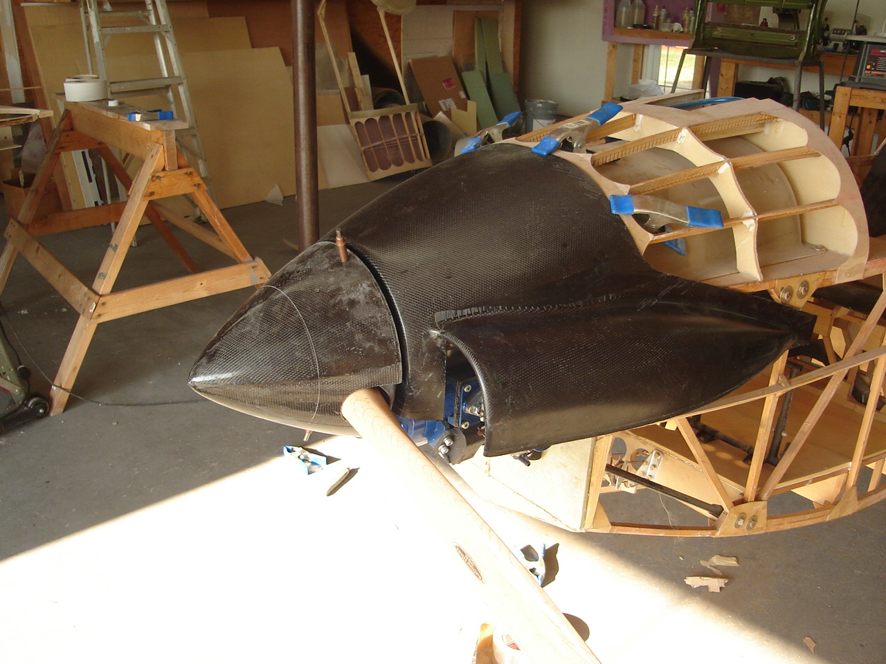
Spinner, ground adjustable prop and upper cowl
Upper cowl trim was previously determined by a fiberglass mock up cowl. I am using 7 oz graphite for the cowl because it is 10 times stiffer than fiberglass and can be laid up with only one ply. The edge bands got a extra doubler. The upper cowl, spinner and backing plate weighs 1lb 1oz.


view looking aft
I'm having a tough time finding metric 8mm x 1.25 grade 8 prop bolts with drilled heads. If anyone has a source please e-mail me at Planebuilder@yahoo.com


R/H side
So while its too hot outside to work, I have been working on a redesigned rudder pedal. I have a fixed seat, since the pilot can weigh as much as the plane, he must be positioned right in the center of the CG range. Consequently the rudder pedals must be adjustable. I had the opportunity 2 weeks ago to take an hour of aerobatic instruction in a ASK 21 sailplane, The rudder pedal adjustment mechanism is similar to an ASW 21 and is pretty typical of German sailplanes. Any way, if its good enough for them, its good enough for me.